Serious Autonomous Vehicles


  • Home

  • Archives

  • Tags

  • Search

mf4 know how

Posted on 2020-07-07 |

preparation

pip reinstall

  • uninstall current pip

  • apt-get install python-pip #which install the default 8.1 version

  • sudo -H pip2 install –upgrade pip #which upgrade to 20.1 version

1
pip install --install-option="--prefix=$PREFIX_PATH" package_name

why does pip3 say I am using v8.1.1, however version 20.1.1 is avail

install asammdf

github: asammdf

it’s recommended to use conda env to manage this project. name this env as mdf. it’s recommended to install packages through conda install, rather than system apt-get install.

the following packages is required:

1
2
3
4
5
6
7
conda install numpy
conda install pandas
conda install -c conda-forge dbus
conda install lxml=4.5.0
conda install -c conda-forge canmatrix
conda install -c conda-forge asammdf
conda install pyqt5 #optionally but recommended, if you need asammdf GUI tool in Linux

take care the pkg installed path, either globally in conda/pkgs/ or in the special env /conda/envs/mdf/lib/python3/site-packages, can simplely import asammdf to see $PYTHONPATH found the module.

conda pythonpath

check existing system path.

1
2
3
import sys
sys.path
['', '/usr/lib/python3/dist-packages', '/home/anaconda3/envs/mf4/lib/python3.8/site-packages']

PYTHON loads the modules from the sys.path in the order, so if PYTHON find the required module in the first PATH, which however is the wrong version, then it’s an error.

does anaconda create a separate PYTHONPATH for each new env: each environment is a completely separate installation of Python and all the packages. there’s no need to mess with PYTHONPATH because the Python binary in the environment already searches the site-packages in that environment, and the libs of the environment.

in one word, when using conda, don’t use system PYTHONPAH

install asammdf[gui]

  • test with PyQt5
1
2
python3
import PyQt5

reports Could not load the Qt platform plugin “xcb” in “” even though it was found

the reason is due to libqxcb.so from ~/anaconda3/envs/aeb/lib/python3.6/site-packages/PyQt5/Qt/plugins/platforms not found libxcb-xinerama.so.0, fixed by install libxcb-xinerama0

1
2
3
ldd libqxcb.so
$ libxcb-xinerama.so.0 => not found
sudo apt-get install libxcb-xinerama0
  • install
1
2
export PYTHONPATH=""
pip install asammdf[gui]
1
2
3
Requirement already satisfied: pyqtgraph==0.11.0rc0; extra == "gui" in /home/gwm/anaconda3/envs/aeb/lib/python3.6/site-packages (from asammdf[gui]) (0.11.0rc0)
Requirement already satisfied: psutil; extra == "gui" in /home/gwm/anaconda3/envs/aeb/lib/python3.6/site-packages (from asammdf[gui]) (5.7.0)
Requirement already satisfied: PyQt5>=5.13.1; extra == "gui" in /home/gwm/anaconda3/envs/aeb/lib/python3.6/site-packages (from asammdf[gui]) (5.15.0)

numpy utils

  • output precision
1
2
3
4
5
6
7
8
res = np.where(arr==roi)
for x in np.nditer(arr):
print(x)
np.set_printoptions(precision=3)
np.set_printoptions(suppress=True)
np.around([], decimals=2)
for (k,v) in dict.items():
print (k, v)

asammdf

bypass non-standard msg

most OEM mdf4 files are collected by Vector CANape tools, which may include many uncommon types, such as Matlab/Simulink objects, measurement signals(multimedia) cam-stream e.t.c, which can’t be parsed by current asammdf tool.

so a simple fix is to bypass these uncommon data type, submit in the git issue.

bytes object to numerical values

bytes objects basically contain a sequence of integers in the range 0-255, but when represented, Python displays these bytes as ASCII codepoints to make it easier to read their contents.

Because a bytes object consist of a sequence of integers, you can construct a bytes object from any other sequence of integers with values in the 0-255 range, like a list:

1
2
bVal = bytes([72, 101, 108, 108, 111])
strVal = bVal.decode('utf-8')

in asammdf, the numerical ndarray can be stored as uint8, uint32, uint64 e.t.c, but with a different range and representation. for radar/camera detected obj id, the range is in [0~255], so here need output as uint8.

sample of ObjID as asammdf.Signal:

1
2
3
4
5
6
7
8
9
10
11
12
13
14
15
16
<Signal MRR_ObjID_3:
samples=[b'' b'' b'' ... b'' b'' b'']
timestamps=[ 0.08185676 0.13073605 0.18073289 ... 57.5313583 57.5813593
57.63134464]
invalidation_bits=None
unit=""
conversion=None
source=<asammdf.blocks.source_utils.Source object at 0x7f79b91c7ae8>
comment="<CNcomment>
<TX/>
<address byte_count="1" byte_order="BE">0x0008</address>
</CNcomment>"
mastermeta="('t', 1)"
raw=False
display_name=
attachment=()>

mf4_reader

first, we need define a high-level APIs to handle collected mf4 from road test. which often includes a bunch of groups for each sensor, and a few channels to record one kind of Signal in one sensor. and another dimension is time, as each Signal is a time serial. the sample Signal output also shows there are two np.narray: samples and timestamps.

1
2
3
-> group
----> channel
--------> samples[timestampIndex]

what we need is to repackage the signals from mf4 as structures of input(mostly like sensor packages) and output(another structure or CAN package) to any model required, e.g. fusion/aeb.

  • init_multi_read(group_name, channel_nums, obj_nums, channel_list)

channel_nums, gives the number of channels/signals for this sensor

obj_nums, is the number of objects can detected by a special sensor, which is given by the vendor of the sensor. e.g. Bosch 5th Radar can detect at most 32 objects.

channel_list, is the name list of the channels, whose length should equal channel_nums.

this API does read all required channels raw data into memeory initially.

  • updateCacheData(group_name, time)

time is the given timestamp, this API returns the interested samples at the given time. one trick here is time matching, as very possiblly, the given time doesn’t match any of the recorded timestamp in a special channel, here always seek the most closest timestamp to time.

  • seek_closest_timestamp_index(timestamps, time)

  • get_channel_data_by_name(channel_name, time)

  • get_channel_all_data_by_name(channel_name)

1
2
3
4
5
6
7
8
9
10
11
12
13
14
15
16
17
18
19
20
from asammdf import MDF4
import numpy as np
class mf4_reader():
def __init__(self, mf4_file):
self.reader = MDF4(mf4_file)
self.channelValsCacheMap = dict()
def init_multi_read(group_name, channel_name, obj_nums, channel_namelist):
channelValuesMap = dict()
for i in range(obj_nums):
for base_name in channel_namelist:
channel_name = base_name + str(i+1)
channel_raw_data = self.get_channel_all_data_by_name(channel_name)
if channel_raw_data :
channelValuesMap[channel_name] = channel_raw_data
else:
channelValuesMap[channel_name] = None
self.channelValsCacheMap[group_name] = channelValuesMap

fusion adapter

once we can read all raw signals from mf4 files, then need to package these signals as the upper-level application requires. e.g. fusion, aeb input structs.

taking fusion module as example. the input includes radar structure, camera structure, e.t.c, something like:

1
2
3
4
5
6
7
8
class radar_sensor_pack():
self.objID,
self.objExistProb ,
self.objDistx,
self.objDisty,
self.objRelVelx,
self.objRelVely,
...

data collection is done by Vector CANape, the sensor pack is defined in *.dbc file, so here basically does package dbc signals to a Python sensor_object, and then assign this sensor_object with the values from mdf4 files.

we need define a bunch of fusion_adapter to package all the necessary inputs for each module, e.g. fusion, aeb e.t.c

rosAdapter

another kind of usage from mf4 file, is transfer mf4 to rosbag. due to most ADS dev/debug/verifcation tools currently are based on ros env. on the other hand, ros base data collection is not robost enough than CANape, so the data collection is in *.mf4.

  • build ros message and define ros_sensor_obj

as asammdf reader is in python, here can build ros message into python module, as mentioned prevously. as ros message built is with catkin_make, which is based on python2.7, so need add the sensor_msgs python module path to $PYTHONPATH in the conda env fusion.

1
export PYTHONPATH=/home/gitlab_/mf4io/linux/toRosbag/catkin_ws/install/lib/python2.7/dist-packages

basically, we use python3 shell, but we add the catkin_ws/python2.7 to its PYTHONPATH.

  • write rosbag

then we can fill in ros_sensor_obj from mf4 structures. and write to bag.

1
self.bag.write('/bose_cr/radar/front_right/object', ros_sensor_obj.data)

rosbag know-how

  • rosbag filter
1
rosbag filter 20200619-xx.bag only-mrr.bag "topic==`/bose_mrr/radar/front/object`"
  • read message from a bag file

refere

lxml

canmatrix

asammdf

what does a b prefix before a python string mean

numpy data type

write rosbag api

record and play back data

ros_readbagfile.py

so ViL, now

Posted on 2020-06-28 |

background

usually Software-in-Loop(SiL) test and verification is defined to cover 90% of all ADS scenarios, then about 9% is test in HiL or ViL, the last 1% is on the real road. so we are on the way to product, so here is ViL.

why ViL ?

Vehicle-in-Loop(ViL) is the last second step in evaluation and verification before releasing a new vehicle product. as ViL is close to the real car system. the benefits is to offer the real vehicle dynamic, which means the real vehicle respond and delay e.t.c.

for functions/features development, ViL also helps to calibrate the boundary of some system parameters, which saves a lot of energy of calibration engineers, as they don’t need to the test field and prepare and run the real vehicles day by day.

how ViL works ?

the logic of ViL is to integrate the real vehicle (dynamic) into a virtual test environment(VTE):

  • forward: the real vehicle send vehicle dynamic data(vehicle position, heading, speed e.t.c) to VTE;

  • backward: VTE split out env information to the real vehicle, which is handled by SoC in vehicle.

so first need prepare a VTE, which has the ability to support external vehicle dynamic(VD) plugin, which is a common feature of VTE, e.g. lgsvl full model interface

secondly, VTE has the ability to export sensor data, which includes exporting data type and exporting data protocol. the common solution is rosbag through ros communication.

ViL in reality

the ideal way of plugin real vehicle dynamic into VTE is throuh full-model-interface(FMI), which is especially true for SiL.

for forward data, vehicle dynamic data here only requies real vehicle position information, which can be obtained in a few ways. from vehicle CAN bus, or from RTK sensor, or from upper application layer, e.g. vehicle status module. but most VTE normally support ros message parsing, rather than CAN message parsing. so additionaly need to define a CAN-ROS message adapter.

for backward data, most VTE(e.g. LG) does have some kind of message channels, e.g. sensor ros topices, which can be used to publish the virtual environment information(sensor data). or VTE may have well-supported sensor message exporter.

limitations

the ViL solution above is an useable and very customized solution, so the extenable ability and data/model precision is limited.

where are you in next 4 years(3)

Posted on 2020-06-28 |

temparately, we have high and low, and of course whether you are a safe-well person tells a lot.

I rejected SxxCVxxW, as the interchange doesn’t tell any difference, the only thing is a new brand and a new office. I am looking for some really changes.

but what’s that ? I still can’t say, maybe recently I am almost lost the focus. things happen recently:

Tesla of course, is leading the rocket rising, with new features in AutoPilot, and new vehicle models always on the way. then Zoox is purchused by Amazon with 1.2 billion USD, how these solution-focused start-ups survive become really interesting now; in China, the top 3 new energy start-ups, namely, Nio, LiXiang, XiaoPeng are beyond self-driving solution lonely, but car makers. and their vehicle model is not that productive, but kind of found a way to survive in Chiese market; the MaaS service providers, such as Didi, Ponyai, WeRide, AutoX are still on the way, and push really harsh to make some noise in Shanghai, Guangzhou and other cities. of course, Waymo, as the top one MaaS service provider globally is also finding its way to break through, just bind to Volvo.

individuals and teams are working really hard to find out the way, but where is the way, or at least what’s the right direction in self-driving in next 5 ~ 10 years. technically, there may be still lots of engineering and research work to do; in bussiniess side, looks car-maker teams are really making some progress, just like Tesla, or other traditional OEMs, they follow the gradually evaluation solution to OTA upgrade the vehciles little by little.

However, it’s just unbelievable to belive OEM teams can lead such a great disruptive innovation in future human life, rather than these innovative and culture-diverse high-tech start-up teams.

there is a foundamental paradox between bussiness and creativity. this is a capital driven bussiness world, every new product is born to create a new needs for human consumers, even more and more needs are unnecessary or anti-human, does this make kind of creativities sound unhuman or irrationaly? I don’t want to answer this question, as I am in one of these teams, and I am even eager to learn how to make success through these creativities.

anyway, I am staying in an OEM supported start-up now, and running on the way to product some model next year. I don’t know where is the way later, and I am afraid this half year is not easy.

play with boost.python 2

Posted on 2020-06-27 |

background

in 1, we have a basic work flow of boost.python. in reality, the C++ project may have multi headers, where define many structs/classes, and include nested structs. here we give an simple example of nested struct/class.

api_header.hpp

1
2
3
4
5
6
7
8
9
typedef struct {
float time;
float dx ;
float dy ;
} AEB;
typedef struct {
AEB out1 ;
} OP;

aeb.hpp

1
2
3
4
5
6
7
8
9
10
11
12
13
14
15
16
17
#include <iostream>
#include <string>
#include "api_header.hpp"
class aeb {
public:
aeb() {}
OP op_out ;
void test_op(){
(void) memset((void *)&op_out, 0, sizeof(OP));
op_out.out1.time = 1.0 ;
op_out.out1.dx = 2.0 ;
op_out.out1.dy = 3.0 ;
AEB o1 = op_out.out1 ;
std::cout << o1.time << std::endl ;
}
};

for each of them, we can write a separate wrapp files.

api_wrapper.cpp

1
2
3
4
5
6
7
8
9
10
11
12
13
14
15
16
17
#include <Python.h>
#include <boost/python.hpp>
#include "api_struct.h"
using namespace boost::python;
BOOST_PYTHON_MODULE(api_wrapper) {
class_<AEB>("AEB", "aeb struct")
.def_readwrite("time", &AEB::time)
.def_readwrite("dx", &AEB::dx)
.def_readwrite("dy", &AEB::dy) ;
class_<OP>("OP", "OP struct")
.def_readwrite("out1", &OP::out1);
}

aeb_wrapper.cpp

1
2
3
4
5
6
7
8
9
10
11
12
13
14
#include <Python.h>
#include <boost/python.hpp>
#include "student.h"
using namespace boost::python;
BOOST_PYTHON_MODULE(aeb) {
scope().attr("__version__") = "1.0.0";
class_<aeb>("aeb", "a class of aeb ADAS")
.def(init<>())
.def(init<std::string, int>())
.def_readwrite("op_out", &aeb::op_out)
.def("test_op", &aeb::test_op, "test op")
}

compared to previous blog, we had def_readwrite() to include the nested struct in aeb python module, which is dynamic linked during python runtime, so which requires to import api_header module first, then import aeb module.

build && test

1
2
3
g++ -I/home/anaconda3/envs/aeb/include/python3.6m -I/usr/local/include/boost -fPIC wrap_api.cpp -L/usr/local/lib/ -lboost_python36 -shared -o wrap_api.so
g++ -I/home/anaconda3/envs/aeb/include/python3.6m -I/usr/local/include/boost -fPIC wrap_student.cpp -L/usr/local/lib/ -lboost_python36 -shared -o student.so
1
2
3
4
5
6
7
import wrap_api
import aeb
s = aeb.aeb()
s.test_op()
a = s.op_out.out1
a.time
a.dx

summary

this basic workflow is enough to package Matlab/Simulink ADAS models C++ code to Python test framework.

boost.python 1

Posted on 2020-06-26 |

background

in OEM’s ADS team, there are bunch of model-based design engineers, who build the ADAS features based on Matlab/Simulink tools, which is good to build quick demos, when comes to massive data verification, we can’t really depends on Matlab solver, which is so slow and licensed.

so a common idea is to recompile the Matlab/Simulink model to C/C++ code, which can further embedded to more open envs, e.g. python or C++.

as previously mentioned, we had designed a rq based massive data driven test framework, so the gap from C++ ADAS code to this python test framework is fixed in this blog.

there are a few wasy to integrate C++ code to Python, one is Boost.Python:

setup

install boost

configuring Boost.BUild

python env : 3.6 (from conda env aeb)
gcc: 4.5.0

1
export BOOST_BUILD_PATH=`pwd` #where we keep `user-config.jam`

user-config.jam

1
2
3
4
5
6
7
8
9
10
11
12
13
14
15
16
using gcc : 5.4.0 : /usr/bin/g++ ;
using python : 3.6
: "/home/anaconda3/envs/aeb/bin/python"
: "/home/anaconda3/envs/aeb/include"
: "/home/anaconda3/envs/aeb/include/python3.6m" ;
```
bootstrap will find `user-config.jam` from $BOOST_BUILD_PATH.
```sh
cd /path/to/boost_1_73_0
./bootstrap.sh --help
./bootstrap.sh --prefix=/usr/local/ --show-libraries
b2 --with-python --prefix="/usr/local/" install variant=release link=static address-model=64
b2 --clean

a sample of user-config.jam

  • error fixing
1
2
fatal error: pyconfig.h: No such file or directory
compilation terminated.

need export CPATH=~/anaconda/envs/aeb/include/python3.6m/, where located pyconfig.h and other headers

finally report: boost.python build successfully !

demo run

the following is simple sample of how to use boost_python wrapper to wrapping an AEB model(in c++) to python

aeb.h

1
2
3
4
5
6
7
8
9
10
11
12
13
14
15
16
17
18
19
20
21
22
23
24
25
26
#include <iostream>
#include <string>
typedef struct {
float time;
float dx ;
float dy ;
} AEB;
typedef struct {
AEB out1 ;
} OP;
class aeb {
public:
Student() {}
OP op_out ;
void test_op(){
(void) memset((void *)&op_out, 0, sizeof(OP));
op_out.out1.time = 1.0 ;
op_out.out1.dx = 2.0 ;
op_out.out1.dy = 3.0 ;
AEB o1 = op_out.out1 ;
std::cout << o1.time << std::endl ;
}
};

wrap_aeb.cpp

1
2
3
4
5
6
7
8
9
10
11
12
13
14
15
16
17
18
19
20
21
22
23
24
25
26
27
28
29
30
31
32
33
34
35
36
37
38
39
40
#include <Python.h>
#include <boost/python.hpp>
#include <boost/python/suite/indexing/vector_indexing_suite.hpp>
#include "aeb.h"
using namespace boost::python;
BOOST_PYTHON_MODULE(aeb) {
scope().attr("__version__") = "1.0.0";
scope().attr("__doc__") = "a demo module to use boost_python.";
class_<aeb>("aeb", "a class of aeb")
.def(init<>())
.def("test_op", &aeb::test_op, "test op")
.def_readonly("op_out", &aeb::op_out)
}
```
tips, if aeb.h and aeb.cpp are separated files, it's better to merge them first; for nested structure in wrapper is another topic later.
#### build and python import
* check header location
Python.h @ `/home/anaconda3/envs/aeb/include/python3.6m`
boost/python @ `/usr/local/include/boost`
* check .so lib location
/usr/local/lib/
tips, if there is duplicated `boost lib` in system, e.g. `/usr/lib/x86_64-linxu-gnu/libboost_python.so` which maybe conflict with `boost_python` install location at `/usr/local/lib/libboost_python36.so`
* build
```sh
g++ -I/home/anaconda3/envs/aeb/include/python3.6m -I/usr/local/include/boost -fPIC wrap_aeb.cpp -L/usr/local/lib/ -lboost_python36 -shared -o aeb.so
  • test
1
2
3
import aeb
t = aeb.aeb
t.test_op()

summary

this blog gives the basic idea how to use boost.python to integrate c++ to python test framework. there are plenty details need fixed, e.g. nested structures, share_pointers. maybe share in next blog.

refere

boost.python tutorial

play with ros 2

Posted on 2020-06-22 |

ros msgs

ros msgs usually used in C++, as our ADS data tool is implemented in Python, I’d try to build *.msg to python module. find two blogs from ROS doc:

writing a ROS python Makefile

create a ros msg

to build msg into python module, the package.yml should at least include the following lines:

1
2
3
4
5
6
<buildtool_depend>catkin</buildtool_depend>
<build_depend>message_generation</build_depend>
<build_export_depend>rospy</build_export_depend>
<build_export_depend>std_msgs</build_export_depend>
<exec_depend>rospy</exec_depend>
<exec_depend>std_msgs</exec_depend>

the default CMakeList.txt looks like:

1
2
3
4
5
6
7
8
9
10
11
12
13
14
15
16
find_package(catkin REQUIED COMPONENTS
roscpp
rospy
std_msgs
message_generation
)
add_message_files(
FILES
custom.msg
)
generate_messages(
DEPENDENCIES
std_msgs
)

the generated msg python module is located at ~/catkin_ws/devel/lib/python2.7/dist-packages/my_msg_py/msg,which can add to $PYTHONPATH for later usage

create ros node with catkin

first check your $ROS_PAKCAGE_PATH, the default pkg path is /opt/ros/kinetic/share, append custom pkgs path from ~/cakin_ws/devel/share.

1
2
3
cd ~/my_catkin_ws/src
catkin_create_pkg my_pkg [dependencies, e.g. sd_msgs rospy]
rospack find

catkin_create_pkg will create a CMakeList.txt at pkg level, and a src folder, where can hold custom nodes definition.

sensor serial data to ros node

sensors(e.g. rtk, imu) to ros is communication from external world to ros sys. Things need to take care: mostly sensor hardware device doesn’t support ROS driver directly, so first need device serial or CAN or Ethernet to get the raw sensor data, and package it as sensor/raw_msg to publish out; the real ros-defined sensor node, will subscribe sensor/raw_msg and publish the repackaged sensor/data to the ros system, (which usually happened in ros callback).

1
2
3
4
5
6
7
8
9
10
11
12
13
14
15
16
17
18
19
20
def rtk_cb(std_msgs::ByteMultiArray raw_msg):
rtk_msg = func(raw_msg)
pub.publish(rtk_msg)
pub = nodeHandler.advertise<sensor_msgs:NavSatFix>("/rtk_gps/data", 1)
sub = nodeHandler.subscribe("/rtk_gps/raw_data", 1, rtk_cb)
def raw_data_generator():
try:
with open("/dev/ttyS0", "r|w") as fd:
header = read(fd, buf, header_line)
while ros::ok():
content = read(fd, buf, content_lines)
std::msgs::ByteMultiArray raw_msg
raw_msg.data.push_back(header)
raw_msg.data.push_back(content)
pub.publish(raw_msg)
close(fd)
except:
print("failed to read raw data\n")

sensor CAN data to ros node

sensors(such as camera, radar, lidar e.t.c) go to ros sys through Veh CAN Bus. the difference between CAN msg and serial msg is data atomicity. as serial msg is only one variable, which gurantee atomicity in application level; while each CAN frame usually include a few variables, which need custom implement atomicity in application level.

1
2
3
4
5
6
7
8
9
10
11
12
13
14
15
16
thread0 = pthread_create(recv_thread, raw_can_data)
thread1 = pthread_create(send_thread)
def thread0():
recv_data = func(raw_can_data)
pthread_mutex_lock(mutex_lock)
sensor_raw = recv_data
sem_post(sem_0)
pthread_mutex_unlock(mutex_lock)
def thread1():
pthread_mutex_lock(mutex_lock)
sensor_ros_msg = sensor_raw
pthread_mutex_unlock(mutex_lock)
node_.publish(sensor_ros_msg)

ros node to external device

another kind of communication, is from ros system to external device/env, such as dSPACE. the external device, if not communication through serial, then usually support Ethernet(udp/tcp), which then need to implement a custom udp/tcp data recv/send func. the ros node subscribe the necessary data, then send it out through udp/tcp.

1
2
3
4
5
def cb(sensor_msg):
data = repack(sensor_msg)
udp.send(data)
sub = nodeHandler.subscribe("/useful/data", 1, cb)

xml-rpc && tcpros

the ros sytem has two communication, to register/update ros node, publish/subscribe topics to ros master. this kind of message go through xml-rpc. after worker nodes registered in master node, the P2P communication can generated, and the data is transfered through tcpros.

each ros node has a xml-rpc server, in code, nodeHandler.advertise() called in publisher/subscriber node, to register their topices to ros master.

once a subscribe node register to master, which topics it subscribed, master returns a URI as response, then the subscriber and publisher can build connection through this URI. when a publish node register to master, master call publisherUpdate() to notify all subscriber, who subscribe topices from this publisher.

ros visual(rviz)

ros-rviz

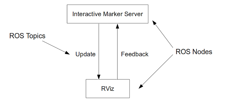
  • how rviz works ?

If you want to create a node providing a set of interactive markers, you need to instantiate an InteractiveMarkerServer object. This will handle the connection to the client (usually RViz) and make sure that all changes you make are being transmitted and that your application is being notified of all the actions the user performs on the interactive markers.

image

  • rviz rosbag

rviz config can customize the rviz display, the default located at ~/.rviz/default.rviz.

the idea to play rosbag and render in rviz is to define a custom node, to receive the custom pkg_msg from replayed rosbag, then repckage pkg_msg as corresponded marker/markerArray, then publish these msg out, which will be received by rviz

usually we define a custom node to receive replayed topics from rosbag.play(), and define a callback func to publish its marker objects out.

1
2
3
4
5
6
7
8
9
10
ros::Publisher markerArray
def pkg_cb(sensor_pkg):
for objIdx in sensor_pkg.ObjNum:
prepare_marker(marker, sensor_pkg.objects[objIdx]
SensorDisplay.markers.append(marker)
markerArray.publish(SensorDisplay)
SensorDisplay->markers.clear()
subPkg = nodeHandler.subscribe("sensor_pkg", 1, pkg_cb);
markerArray = nodeHandler.advertise<visulization_msgs::MarkerArray>("sensor_pkg", 1)

ros summary

ros is a very common communciation way and message type in ADS dev, many demo are implemented based on ros, which gives a bunch of ros related tools. in this blog, we review three of them:

  • ros based sensor device data collection
  • ros rviz
  • rosbag.play

which can support a few kinds of applications, e.g. debuging, replay, data collection.

redis queue(rq) in data processing

Posted on 2020-06-04 |

background

recently thinking about how to design middleware and frameworks in self-driving team, just like the back-end service in most web servicees, which gives the way to go uppper and go abstract. currently many start-up ADS team, espcially Internet-based start-ups, have built-in ADS frameworks and middlewares, to support their daily dev and easily to implement new features. here is an old topic, redis task queue, how to design a robost data pipeline to support ADAS/ADS functions virtual test with physical collected road data.

the experience to put lgsvl into swarm/k8s brings the idea about micro-services, which is a great way to decouple a large work to a few small pieces of independent but communicatable services. so when coming to handle large data set, which is very common in ADS dev.

so the first idea is to decouple the data pipeline as a few micro-services: reader service, process service, post-analysis service e.t.c

then two questions immediately up: which data/message type fits, which network communication protocol fits.and beyond these two basic questions, also need a lot work about message adapter among/in services. previously, I designed websocket and json solution. but it’s too tedious to plug in a ws-server/client at the front/end of each service, especially as the number of serivces grows.

take it back, data pipeline is a heavy data IO work, is it really smart to split the work into a few pieces, then find the network communication among them ? we increase the system complex by introducing additional network communcation moduels, and the only benefit is decouple a heavy data IO work. and more, the network modules need consider cache, job scheduler, load balance issues, as the data process service may take much longer than reader services.

traditionally, heavy data IO work is common run in batch processing, disregarding network issues, and it’s better to run directly in memory/cache. so I go to rq

interprocess communication in distributed system

MPI is the standard for IPC in HPC apps, of course there are Linux IPC libs, which brings more low-level ipc APIs. MPI apps mostly run on high performance computing cluster, which has the samilar API e.g. Allreduce as Hadoop/MapReduce, while the difference MPI/allReduce doesn’t tolerate failure, which means any node failed, the MPI apps failed. Which is the foundmental difference from HPC to distributed system nowadays, really popular as the new infrastructure for cloud and AI.

in the distributed system, there are a few ways to do interprocess communication:

  • RESTful protocol, such as TCP, UDP, websocket.

  • async communication, there are different ways to implement async interprocess communication, one way is message queue, of course many language, e.g. js, go have some light-weight libs/framework to support ansyc communication interprocessly.

  • rpc, thrift is an Apache project, grpc is high efficient with protobuf, but it doesn’t support well service discovery/load balance mechanism inside, which is a limitation in cloud-native applications. dubbo has a better design for service discovery and load balance, the message type by default is json. so all of these can be the corner-stone service in modern micro service envs. also the common micro-service framework, e.g. Spring Cloud has interprocess communication component as well.

for data hungry services, batch processing frameworks, e.g. Spring Batch, Linux Parallel should also consider.

rq

the following is from rq doc

Queues

a job is a Python object, namely a function that is invoked async in a worker process. enqueueing is simply pushing a reference to the func and its ars onto a queue.

we can add as many Queue instance as we need in one Redis instance, the Queue instance can’t tell each other, but they are hosted in the same redis instance, which gives the way to find jobs binding to Queue1 in worker2 from Queue2

jobs

1
2
3
job1 = q.enqueue(my_func, func_args)
job2 = Job.create(my_func, ttl=100, failure_ttl=10, depends_on=, description=, func_args)
q.enqueue_job(job2)
  • timeout: specifies the max runtime of job before it’s interrupted and marked as failed.
  • ttl: specifies the maximum queued time(in sec) of the job before it’s dscarded. default is None(infinite TTL)
  • failure_ttl: specifies how long(in sec) failed jobs are kept(default to 1 years)

the following sample is a way to find all rq:job:s, but the return is a bytes object, which need encode as utf-8 for any further usage.

1
2
3
4
5
import redis
r = redis.StrictRedis()
r.keys()
for key in r.scan_iter("rq:job:*"):
print(key.encode('utf-8')

workers

workers will read jobs from the given queues(the order is important) in an endless loop, waiting for new work to arrive when all jobs done. each worker will process a single job at a time. by default, workers will start working immediately and wait until new jobs. another mode is burst, where to finish all currently avaiable work and quit asa all given queues are emptied.

rq worker shell script is a simple fetch-fork-execute loop

connections

when you want to use multiple connections, you should use Connection contexts or pass connections around explicitly.

1
2
3
4
5
conn1 = Redis('localhost', 6379)
conn2 = Redis('remote.host.org', 9836)
q1 = Queue('foo', connection=conn1)
q2 = Queue('bar', connection=conn2)

Every job that is enqueued on a queue will know what connection it belongs to. The same goes for the workers.
within the Connection context, every newly created RQ object instance will have the connection argument set implicitly.

1
2
3
4
5
def setUp(self):
push_connection(Redis())
def tearDown(self):
pop_connection()

this should be the way to handle distributed queues.

results

if a job returns a non-None value, the worker will write that return value back to the job’s Redis hash under result key. the job’s Redis hash itself expire in 500sec by default after the job is finished.

1
2
q.enqueue(foo, result_ttl=86400) # result expires after 1 day
q.enqueue(func_without_rv, result_ttl=500) # job kept explicitly

when an exception is thrown inside a job, it’s caught by the worker, serialized and stored under exc_info key. By default, jobs should execute within 180 seconds. After that, the worker kills the work horse and puts the job onto the failed queue, indicating the job timed out.

1
q.enqueue(mytask, args=(foo,), kwargs={'bar': qux}, job_timeout=600) # 10 mins

job registries

each queue maintains a set of Job Registries. e.g. StartedJobRegistry, FinishedJobRegistry e.t.c. we can find these after log in redis-cli

version bug

when run rq demo, it reports:

1
2
raise RedisError("ZADD requires an equal number of "
redis.exceptions.RedisError: ZADD requires an equal number of values and scores

manually change /rq/registry.py:

1
2
# return pipeline.zadd(self.key, {job.id: score})
return pipeline.zadd(self.key, job.id, score)

data pipeline for ADS function verification

  • queues

each queue instance can be taken as a separate namespace in the Redis instance, so the workers only process the jobs in the same queue. but if multi-queues are hosted in the same Redis instance, then Redis api can find Queue A’s jobs in Queue B’s workers.

1
2
3
4
conn = Redis()
mf4q = Queue('mf4Q', connection=conn)
aebq = Queue('aebQ', connection=conn)
dbq = Queue('dbQ', connection=conn)
  • jobs

if the handler_fun has return values, namely status. rq store its status at job.result, thle lifecycle of which can be controlled by result_ttl, e.t.c.

to control the order of running the jobs, jobs can have depend.

1
2
3
4
5
6
7
8
def mf4_jober(url_path):
mf4_job = mf4q.enqueue(mf4_reader, args=(url_path,), timeout=60, ttl=60, failure_ttl=1, job_timeout=60, result_ttl=60, job_id=mf4_job_id)
def aeb_jober(mf4_frames):
aeb_job = aebq.enqueue(aeb_oneStep, args=(i_, ), timeout=60, ttl=20, failure_ttl=1, result_ttl=10, job_id=aeb_job_id)
def db_jober(aeb_frame, idx):
db_job= dbq.enqueue(db_oneStep, args=(aeb_frame,), timeout=60, ttl=20, failure_ttl=1, job_id=db_job_id)
  • workers
1
2
3
4
5
6
7
8
def mf4_workers(conn, num_workers=1):
for i in range(num_workers):
worker_ = Worker([mf4q], connection=conn, name=worker_name)
workers_.append(worker_)
for w in workers_:
w.work(burst=True)
def aeb_workers()
def db_workers()
  • runners
1
2
3
4
5
6
7
8
def runner(conn):
mf4_workers(conn)
for k in conn.scan_iter("rq:job:mf4_job_*"):
t_ = k.decode('utf-8')
j_ = Job.fetch(t_[7:], connection=conn)
aeb_jober(j_.result)
input("hold on ...")
aeb_workers(conn)

since the output of mf4 jobs is the input of aeb, so we need runners, similar for db.

summary

rq is a good framework for this level data pipleine. for even bigger and complex system, rq maybe just a middleware, and there should be an even larger framework. the software engineering idea about framework and middleware in a large system gradually become the foundataion of ADS team

in distributed system, there are a few basic concepts distributed consensus, the popular choice e.g. zookeeper, etcd; interprocess communication, distributed cache e.t.c. really cool to know.

refer

xiaorui blog: rq

微服架构中的进程间通信

微服务架构

使用gRPC构建微服务

微服务, 通信协议对比

理解批处理的关键设计

spring batch 批处理

Linux iptables

Posted on 2020-05-23 |

background

从iptable详解整理的。 理解iptables,是为了更好的理解k8s中网络。

从逻辑上讲。防火墙可以大体分为主机防火墙和网络防火墙。

主机防火墙:针对于单个主机进行防护。

网络防火墙:往往处于网络入口或边缘,针对于网络入口进行防护,服务于防火墙背后的本地局域网。

iptables其实不是真正的防火墙,我们可以把它理解成一个客户端代理,用户通过iptables这个代理,将用户的安全设定执行到对应的”安全框架”中,这个”安全框架”才是真正的防火墙,这个框架的名字叫netfilter

Netfilter是Linux操作系统核心层内部的一个数据包处理模块,它具有如下功能:

  • 网络地址转换(Network Address Translate)

  • 数据包内容修改

  • 以及数据包过滤的防火墙功能

规则一般的定义为”如果数据包头符合这样的条件,就这样处理这个数据包”. 规则分别指定了源地址、目的地址、传输协议(如TCP、UDP、ICMP)和服务类型(如HTTP、FTP和SMTP)等. 当数据包与规则匹配时,iptables就根据规则所定义的方法来处理这些数据包,如放行(accept)、拒绝(reject)和丢弃(drop)等。配置防火墙的主要工作就是添加、修改和删除这些规则。

如果我们想要防火墙能够达到”防火”的目的,则需要在内核中设置关卡,所有进出的报文都要通过这些关卡,经过检查后,符合放行条件的才能放行,符合阻拦条件的则需要被阻止,于是,就出现了input关卡和output关卡,而这些关卡在iptables中不被称为”关卡”,而被称为”链”。当客户端发来的报文访问的目标地址并不是本机,而是其他服务器,当本机的内核支持IP_FORWARD时,我们可以将报文转发给其他服务器。这个时候,我们就会提到iptables中的其他”关卡”,也就是其他”链”,他们就是 “路由前”、”转发”、”路由后”,他们的英文名是

PREROUTING、FORWARD、POSTROUTING

image

当我们定义iptables规则时,所做的操作其实类似于”增删改查”。

“关卡“/”链“ 包括: prerouting, INPUT, OUTPUT, FORWARD, POSTROUTING

表: filter 负责过滤(iptables_filter); nat(network address translation), 网络地址转发, mangle, raw

表名:

1
iptables -t filter -L (INPUT/OUTPUT/FORWARD/DOCKER-USER/DOCKER-ISOLATION-STAGE/KUBE-EXTERNAL-SERVICES/KUBE-FIREWALL/UBE-FORWARD/KUBE-KUBELET-CANARY/KUBE-SERVICES)

-t选项,查看表名(filter/mangle/nat)
-L 选项,规则/链名
-n 选项,表示不对IP地址进行名称反解,直接显示IP地址。
–line-number 选项, 显示规则的编号

规则大致由两个逻辑单元组成,匹配条件与动作。

  • 测试1:拒绝某个远程主机(10.20.180.12)访问当前主机(10.20.181.132)
1
iptables -t filter -I INPUT -s 10.20.180.12 -j DROP
  • -I 选项, 插入规则到哪个链
  • -s 选项,匹配条件中的源地址
  • -j 选项,当匹配条件满足,采取的动作
  • 测试1.1:拒绝某个远程主机(10.20.180.12)访问当前主机(10.20.181.132),再追加一条接受(10.20.180.12)的访问
1
iptables -A INPUT -s 10.20.180.12 -j ACCEPT
  • -A选项,追加规则到某个链。

不通 即规则的顺序很重要。如果报文已经被前面的规则匹配到,iptables则会对报文执行对应的动作,即使后面的规则也能匹配到当前报文,很有可能也没有机会再对报文执行相应的动作了。

  • 测试2: 根据规则编号去删除规则
1
2
iptables --line -vnL INPUT
iptables -t filter -D INPUT N
  • -D选项,删除某条链上的第N条规则
  • 测试2.2: 根据具体的条件去执行删除规则
1
2
iptables -vnL INPUT
iptables -t filter -D INPUT -s 10.20.180.12 -j DROP

修改规则,一般就是删除旧规则,再添加新规则。

  • 保存规则

当重启iptables服务或者重启服务器以后,我们平常添加的规则或者对规则所做出的修改都将消失,为了防止这种情况的发生,我们需要将规则”保存”

1
2
iptables-save > /etc/network/iptables.up.rules
iptables-apply #restart iptables
  • 更多关于匹配条件

    -s 选项, 指定源地址作为匹配条件,还可以指定一个网段,或用 逗号分割多个IP; 支持取反。

    -d 选项,指定目标地址作为匹配条件。

不指定,默认就是(0.0.0.0/0),即所有IP

-p 选项,指定匹配的报文协议类型。

1
2
iptables -t filter -I INPUT -s 10.20.180.12 -d 10.20.181.132 -p tcp -j REJECT
ssh 10.20.180.12 #from 10.20.181.132 ssh t0 10.20.180.12 suppose to be rejected. but not ?

-i选项,匹配报文通过哪块网卡流入本机。

iptables之网络防火墙

当外部网络中的主机与网络内部主机通讯时,不管是由外部主机发往内部主机的报文,还是由内部主机发往外部主机的报文,都需要经过iptables所在的主机,由iptables所在的主机进行”过滤并转发”,所以,防火墙主机的主要工作就是”过滤并转发”

image

主机B也属于内部网络,同时主机B也能与外部网络进行通讯,如上图所示,主机B有两块网卡,网卡1与网卡2,网卡1的IP地址为10.1.0.3,网卡2的IP地址为192.168.1.146:

image

c主机网关指向B主机网卡1的IP地址;A主机网关指向B主机网卡2的IP地址。

on hostmachine A:

1
2
3
route add -net 10.1.0.0/16 gw 192.168.1.146
ping 10.1.0.1 # ping machine C, not available
ping 10.1.0.3 # ping machine B(NIC 2), avaiailable
  • 为什么10.1.0.1没有回应。

A主机通过路由表得知,发往10.1.0.0/16网段的报文的网关为B主机,当报文达到B主机时,B主机发现A的目标为10.1.0.1,而自己的IP是10.1.0.3,这时,B主机则需要将这个报文转发给10.1.0.1(也就是C主机),但是,Linux主机在默认情况下,并不会转发报文,如果想要让Linux主机能够转发报文,需要额外的设置,这就是为什么10.1.0.1没有回应的原因,因为B主机压根就没有将A主机的ping请求转发给C主机,C主机压根就没有收到A的ping请求,所以A自然得不到回应

  • 为什么10.1.0.3会回应。

这是因为10.1.0.3这个IP与192.168.1.146这个IP都属于B主机,当A主机通过路由表将ping报文发送到B主机上时,B主机发现自己既是192.168.1.146又是10.1.0.3,所以,B主机就直接回应了A主机,并没有将报文转发给谁,所以A主机得到了10.1.0.3的回应

  • 如何让LINUX主机转发报文

check /proc/sys/net/ipv4/ip_forward. if content is 0, meaning the Linux hostmachine doesn’t forward; if content is 1, meaning the Linux hostmachine does forward.

or

1
sysctl -w net.ipv4.ip_forward=1

for permenentally allow Linux host forward, update file /etc/sysctl.conf.

设置linux主机转发报文后, A ping C || C ping A should works.

如果我们想要使内部的主机能够访问外部主机的web服务,我们应该怎样做呢? 我们需要在FORWARD链中放行内部主机对外部主机的web请求.

  • 在B主机上:
1
2
iptables -I FORWARD -j REJECT
iptables -I FORWARD -s 10.1.0.0/16 -p tcp --dport 80 -j ACCEPT

B主机上所有转发(forward)命令,都REJECT。只ACCEPT 内网10.1.0.0/16 网段, 端口80的转发FORWARD. (即内网网段可访问外网)。 C ping A (ok)

destnation port 目标端口。

想让A ping C, 需在B主机iptables中再添加如下规则:

1
iptables -I FORWARD -d 10.1.0.0/16 -p tcp --sport 80 -j ACCEPT

source port 源端口。

配置规则时,往往需要考虑“双向性”。因为一条规则(forward),只会匹配最新的规则定义。上述修改完了,A 可以PING C,但C又PING不通A了。 a better way, no matter request from in to out or the othersize, both should FORWARD.

1
iptables -I FORWARD -m state --state ESTABLISHED,RELATED -j ACCEPT
  • 更多动作

NAT, network address translation. 网络地址转换。NAT说白了就是修改报文的IP地址,NAT功能通常会被集成到路由器、防火墙、或独立的NAT设备中。那为什么要修改报文的IP地址呢?

scenario1 :网络内部有10台主机,它们有各自的IP地址,当网络内部的主机与其他网络中的主机通讯时,则会暴露自己的IP地址,如果我们想要隐藏这些主机的IP地址,该怎么办呢?

当网络内部的主机向网络外部主机发送报文时,报文会经过防火墙或路由器,当报文经过防火墙或路由器时,将报文的源IP修改为防火墙或者路由器的IP地址,当其他网络中的主机收到这些报文时,显示的源IP地址则是路由器或者防火墙的,而不是那10台主机的IP地址,这样,就起到隐藏网络内部主机IP的作用。同时路由器会维护一张NAT表,记录这个内部主机的IP和端口。当外部网络中的主机进行回应时,外部主机将响应报文发送给路由器,路由器根据刚才NAT表中的映射记录,将响应报文中的目标IP与目标端口再改为内部主机的IP与端口号,然后再将响应报文发送给内部网络中的主机。

刚才描述的过程中,”IP地址的转换”一共发生了两次。

内部网络的报文发送出去时,报文的源IP会被修改,也就是源地址转换:Source Network Address Translation,缩写为SNAT。

外部网络的报文响应时,响应报文的目标IP会再次被修改,也就是目标地址转换:Destinationnetwork address translation,缩写为DNAT。

不论内网访问外网,Or the otherwise。都会有上述两次IP转换。一般将内网请求外网服务称为snat,外网请求内网服务称为dnat.

上述场景不仅仅能够隐藏网络内部主机的IP地址,还能够让局域网内的主机共享公网IP,让使用私网IP的主机能够访问互联网。比如,整个公司只有一个公网IP,但是整个公司有10台电脑,我们怎样能让这10台电脑都访问互联网呢? 只要在路由器上配置公网IP,在私网主机访问公网服务时,报文经过路由器,路由器将报文中的私网IP与端口号进行修改和映射,将其映射为公网IP与端口号,这时,内网主机即可共享公网IP访问互联网上的服务了

场景2:公司有自己的局域网,网络中有两台主机作为服务器,主机1提供web服务,主机2提供数据库服务,但是这两台服务器在局域网中使用私有IP地址,只能被局域网内的主机访问,互联网无法访问到这两台服务器,整个公司只有一个可用的公网IP。如何让公网访问到公司的内网服务呢?

将这个公网IP配置到公司的某台主机或路由器上,然后对外宣称,这个IP地址对外提供web服务与数据库服务,于是互联网主机将请求报文发送给这公网 IP地址,也就是说,此时报文中的目标IP为公网IP,当路由器收到报文后,将报文的目标地址改为对应的私网地址,比如,如果报文的目标IP与端口号为:公网IP+3306,我们就将报文的目标地址与端口改为:主机2的私网IP+3306,同理,公网IP+80端口映射为主机1的私网IP+80端口,当私网中的主机回应对应请求报文时,再将回应报文的源地址从私网IP+端口号映射为公网IP+端口号,再由路由器或公网主机发送给互联网中的主机。

测试环境,同ABC主机。
  • SNAT 测试

on B hostmachine:

1
iptables -t nat -A POSTROUTING -s 10.1.0.0/16 -j SNAT --to-source 192.168.1.146

SNAT规则只能存在于POSTROUTING链与INPUT链中。 “–to-source”就是SNAT动作的常用选项,用于指定SNAT需要将报文的源IP修改为哪个IP地址。此处,即B的公网IP.

  • DNAT测试

on B machine:

1
2
iptables -t nat -F #flash nat table
iptables -t nat -I PREROUTING -d 192.168.1.146 -p tcp --dport 3389 -j DNAT --to-destination 10.1.0.6:3389

-j DNAT –to-destination 10.1.0.6:3389”表示将符合条件的报文进行DNAT,也就是目标地址转换,将符合条件的报文的目标地址与目标端口修改为10.1.0.6:3389。 理论上只要完成上述DNAT配置规则即可,但是在测试时,只配置DNAT规则后,并不能正常DNAT,经过测试发现,将相应的SNAT规则同时配置后,即可正常DNAT,于是我们又配置了SNAT:

1
iptables -t nat -A POSTROUTING -s 10.1.0.0/16 -j SNAT --to-source 192.168.1.146

MASQUERADE

当我们拨号网上时,每次分配的IP地址往往不同,不会长期分给我们一个固定的IP地址,如果这时,我们想要让内网主机共享公网IP上网,就会很麻烦,因为每次IP地址发生变化以后,我们都要重新配置SNAT规则,这样显示不是很人性化,我们通过MASQUERADE即可解决这个问题。

MASQUERADE会动态的将源地址转换为可用的IP地址,其实与SNAT实现的功能完全一致,都是修改源地址,只不过SNAT需要指明将报文的源地址改为哪个IP,而MASQUERADE则不用指定明确的IP,会动态的将报文的源地址修改为指定网卡上可用的IP地址。

1
iptables -t nat -I POSTROUTING -s 10.1.0.0/16 -o en1 -j MASQUERADE

通过B外网网卡出去的报文在经过POSTROUTING链时,会自动将报文的源地址修改为外网网卡上可用的IP地址,这时,即使外网网卡中的公网IP地址发生了改变,也能够正常的、动态的将内部主机的报文的源IP映射为对应的公网IP。

可以把MASQUERADE理解为动态的、自动化的SNAT

REDIRECT

使用REDIRECT动作可以在本机上进行端口映射

1
iptables -t nat -A PREROUTING -p tcp --dport 80 -j REDIRECT --to-ports 8080

经过上述规则映射后,当别的机器访问本机的80端口时,报文会被重定向到本机的8080端口上。
REDIRECT规则只能定义在PREROUTING链或者OUTPUT链中。

refer

iptables essentials

ip route, ip rule & iptables 知多少

k8s: flannel

Posted on 2020-05-23 |

background

k8s networks include a few topics:

  • pod to pod communication in k8s

  • pod to the host node communication

  • pod to external service URL

  • external request to pod in k8s

the networks have two components: DNS and iptables. DNS used to resovle URL name to IP; iptables used to control network message transfer in/out.

preparation image for test

to test network inside pod/docker, we need add the following network tools:

1
2
3
4
5
iputils-ping \
net-tools \
iptables \
iproute

docker/pod runtime privileges

by default, docker doesn’t allow run iptables inside container. and it give errors:

1
2
3
root@redisjq:/# iptables -t nat -L | grep INPUT
iptables v1.6.0: can't initialize iptables table `nat': Permission denied (you must be root)
Perhaps iptables or your kernel needs to be upgraded.

which need to add docker runtime privilege and Linux capabilities

container capabilities in k8s

In a Kubernetes pod, the names are the same, but everything has to be defined in the pod specification. When implementing this in Kubernetes, you add an array of capabilities under the securityContext tag.

1
2
3
4
securityContext:
capabilities:
add:
- NET_ADMIN

k8s pod DNS

DNS for services and pods introduced four types:

  • None

  • Default, where POD derived DNS config from the host node where to run pod.

  • ClusterFirst, where POD use DNS info from kube-dns or coreDNS

  • ClusterFirstWithHostNet, as the name explained.

tips, Default is not the default DNS policy. If dnsPolicy is not explicitly specified, then ClusterFirst is used as default.

the purpose of pod/service DNS is used to transfer URL to IP, which is the second step after iptabels is understand successfully.

coreDNS is setted during kube-adm init with serverDNS. To do SNAT, the pod/service in K8S need access

resolv.conf/DNS inside pod :
1
2
3
4
root@redisjq:/redis# cat /etc/resolv.conf
nameserver 10.96.0.10
search lg.svc.cluster.local svc.cluster.local cluster.local
options ndots:5

clearly, the pod DNS is coming from cluster, which can be check by:

1
2
3
4
5
6
7
8
kubectl describe configmap kubeadm-config -n kube-system
kind: ClusterConfiguration
kubernetesVersion: v1.18.2
networking:
dnsDomain: cluster.local
podSubnet: 10.4.0.0/16
serviceSubnet: 10.96.0.0/12

and that’s the reason why resolve URL failed, as clusterDNS is kind of random defined.

the DNS failure gives errors as following inside pod:

1
socket.gaierror: [Errno -3] Temporary failure in name resolution

docker0 DNS

docker engine can configure its DNS at /etc/daemon.json, with “dns” section. when running docker in single mode, docker0 looks has host machine’s DNS, but when runnig in swarm mode, need to define additional DNS for external access.

iptables in K8S

docker and iptables

you should not modify the rules Docker inserts into your iptables policies. Docker installs two custom iptables chains named DOCKER-USER and DOCKER, and it ensures that incoming packets are always checked by these two chains first

a simple test can found, docker0 NIC is bridge is well to bind host network namespace, either export or response request externally. while with flannel.d NIC, pod can’t access external resources.

code review: kube-proxy iptables:

iptables has 5 tables and 5 chains.

the 5 chaines:

1
2
3
4
5
PREROUTING: before message into route, the external request DNAT.
INPUT: message to local host or current network namespace.
FORWARD: message forward to other host or other network namespace.
OUTPUT: message export from current host
POSTROUTING: after route before NIC, message SNAT

the 5 tables:

1
2
3
4
5
filter table, used to control the network package need to ACCEPT, or DROP, or REJECT when it comes to a chain
nat(network address translation) table, used to modify the src/target address of network package
mangle table, used to modify IP header info of network package
raw table
security table

for k8s pods/services, mostly consider filter and nat tables. and k8s expand another 7 chains: KUBE-SERVICES、KUBE-EXTERNAL-SERVICES、KUBE-NODEPORTS、KUBE-POSTROUTING、KUBE-MARK-MASQ、KUBE-MARK-DROP、KUBE-FORWARD.

image

virtual network flannel

check running flanneld

  • /etc/cni/net.d/10-flannel.conflist on host machine is the same as /etc/kube-flannel/cni-conf.json in flannel container on master node.

  • /run/flannel/subnet.env exist in both flannel container (on master node) and in master host machine. it looks like network configure(subnet.env) is copied from container to host machine. so if there is no flannel container running on some nodes, these nodes won’t have the right network configure.

at master node, HostPath points to: /run/flannel, /etc/cni/net.d, kube-flannel-cfg (ConfigMap); while at working node(due to missing /gcr.io/flannel image), /run/flannel/subnet.env is missed. previously, I thought to cp this file from master node to woker node is the solution, then this file is missed every time to restart worker node.

once copied both kube-proxy and flannel images to worker node, and restart kubelet at worker node, the cluster should give Running status of all these components. including 2 copies of flannel, one running on master node, and the other running on working node.

as we are using kubectl to start the cluster, the actual flanneld is /opt/bin/flanneld from the running flannel container, and it maps NIC to the host machine.

another thing is, flannel is the core of the default kube-proxy, so kube-proxy image is also required on both nodes. coreDNS run two copies on master node.

Flannel mechanism

the data flow: the sending message go to VNC(virtual network card) docker0 on host machine, which transfers to VNC flannel0. this process is P2P. the global etcd service maintain a iptables among nodes, which store the subnet range of each node. 2) the flanneld service on the special node package the sending message as UDP package, and delivery to target node, based on the iptables. 3) when the target node received the UDP package, it unpackage the message, and send to its flannel0, then transfer to its docker0.

1) after flanneld started,will create flannel.1 virtual network card. the purpose of flannel.1 is for across-host network, including package/unpackage UDP, and maintain iptables among the nodes.

2) each node also create cni0 virtual network card, at the first time to run flannel CNI. the purpose of cni0 is same as docker0, and it’s a bridge network, used for communication in the same node.

image

test with redis services

we had define a redisjq pod, the following testes are all in this pod:

1
2
3
4
5
6
7
8
9
kubectl exec -it redisjq -n lg /bin/bash
ping localhost #ok
ping 10.255.18.3 #not
ping 10.3.101.101 #not
ping 10.20.180.12
ifconfig
>>eth0, 10.4.1.46
>>lo, 127.0.0.1

the output above is initial output before we had any network setttings. basically the pod can only ping localhost, neither the host DNS, or the host IP. the vip(10.4.1.46) is not in the same network namespace as host network space.

flannel.d pod on both nodes:

1
2
3
4
5
6
7
david@meng:~/k8s/lgsvl$ kubectl get pods kube-flannel-ds-amd64-85d6m -n kube-system --output=wide
NAME READY STATUS RESTARTS AGE IP NODE NOMINATED NODE READINESS GATES
kube-flannel-ds-amd64-85d6m 1/1 Running 5 15d 10.20.180.12 meng <none> <none>
david@meng:~/k8s/lgsvl$ kubectl get pods kube-flannel-ds-amd64-fflsl -n kube-system --output=wide
NAME READY STATUS RESTARTS AGE IP NODE NOMINATED NODE READINESS GATES
kube-flannel-ds-amd64-fflsl 1/1 Running 154 15d 10.20.181.132 ubuntu <none> <none>

flannel.d is runing on each node, should triggered by kubelet. flannel.d is used as virtual network interface, to manage across-node pod communication inside k8s.

coredns pod in meng node

1
2
3
david@meng:~/k8s/lgsvl$ kubectl get pods coredns-66bff467f8-59g97 -n kube-system --output=wide
NAME READY STATUS RESTARTS AGE IP NODE NOMINATED NODE READINESS GATES
coredns-66bff467f8-59g97 1/1 Running 4 14d 10.4.0.27 meng <none> <none>

coredns has two replicas, both running on master node(meng), and we can see it only has virtual ip/cluster ip ( 10.4.0.x).

redisjs pod in ubuntu’s node

1
2
3
david@meng:~/k8s/lgsvl$ kubectl get pods redisjq -n lg --output=wide
NAME READY STATUS RESTARTS AGE IP NODE NOMINATED NODE READINESS GATES
redisjq 1/1 Running 0 20m 10.4.1.47 ubuntu <none> <none>

by default, working pod is only running at woker node(ubuntu), which has clusterIP(10.4.1.47).

pod1 ping pod2 in the same node

ping successfully there is no doubt in the same node, pods can ping each other.

redisjq pod1(10.4.1.47) in ubuntu ping corends pod2(10.4.0.27) in meng

1
2
3
root@redisjq:/redis# ping 10.4.0.27
PING 10.4.0.27 (10.4.0.27) 56(84) bytes of data.
64 bytes from 10.4.0.27: icmp_seq=1 ttl=62 time=0.757 ms

ping successfully, which is the working of flanneld.

redisjq pod1(10.4.1.7) in ubuntu ping hostIP(10.20.181.132) of ubuntu

1
2
3
root@redisjq:/redis# ping 10.20.181.132
PING 10.20.181.132 (10.20.181.132) 56(84) bytes of data.
64 bytes from 10.20.181.132: icmp_seq=1 ttl=64 time=0.127 ms

ping successfuly, pod in cluster can ping its host node, sounds no problem.

redisjq pod1(10.4.1.7) in ubuntu ping hostIP(10.20.180.12) of meng

1
2
root@redisjq:/redis# ping 10.20.180.12
PING 10.20.180.12 (10.20.180.12) 56(84) bytes of data.

ping failed, interesting, so pod in cluster can’t ping any non-hosting node’s IP.

so far, pod with vip can ping any other pod with vip in the cluster, no matter in the same node or not. pod with vip can only ping its host machine’s physical IP, but pod can’t ping other hostIP.

namely, the network of pod VIP inside k8s and the bridge network from pod vip to its host is set well. but the network from pod to external IP is not well.

these 4 tests give a very good understanding about flannel’s function inside k8s: pod to pod in the same node or not. but usually we need SNAT or DNAT. to make SNAT/DNAT avaiable, we need understand DNS & iptables of k8s.

update iptables to allow pod access public IP

cni0, docker0, eno1, flannel.1 in host machine vs eth0 in pod

these virtual NIC are common in k8s env.

  • on node1
1
2
3
4
cni0: 10.4.1.1
docker0: 172.17.0.1
eno1: 10.20.181.132
flannel.1: 10.4.1.0
  • on pod1, which is running on node1
1
eth0: 10.4.1.48

pod1 -> pod2 network message flow

1
pod1(10.4.1.48) on node1(10.20.181.132) -> cni0(10.4.1.1) -> flannel.1(10.4.1.0) -> kube-flannel on node1(10.20.181.132) -> kube-flannel on node2(10.20.180.12) -> flannel.1 on node2 -> cni0 on node2 -> pod2(10.4.1.46) on node2

to allow network message SNAT, namely to handle FORWARD internal clusterIP data to external services, we can add the following newe iptable rule:

1
iptables -t nat -I POSTROUTING -s 10.4.1.0/24 -j MASQUERADE

after add the new rule, check inside pod:

1
2
3
4
5
6
7
8
9
10
11
12
13
14
root@redisjq:/redis# ping 10.20.180.12
PING 10.20.180.12 (10.20.180.12) 56(84) bytes of data.
64 bytes from 10.20.180.12: icmp_seq=1 ttl=62 time=0.690 ms
root@redisjq:/redis# ping 10.20.181.132
PING 10.20.181.132 (10.20.181.132) 56(84) bytes of data.
64 bytes from 10.20.181.132: icmp_seq=1 ttl=64 time=0.108 ms
root@redisjq:/redis# ping 10.20.180.61
PING 10.20.180.61 (10.20.180.61) 56(84) bytes of data.
64 bytes from 10.20.180.61: icmp_seq=1 ttl=126 time=0.366 ms
root@redisjq:/redis# ping www.baidu.com
ping: unknown host www.baidu.com
root@redisjq:/redis# ping 61.135.169.121 #baidu IP
PING 61.135.169.121 (61.135.169.121) 56(84) bytes of data.
64 bytes from 61.135.169.121: icmp_seq=1 ttl=51 time=8.16 ms

the DNS is not fixed, so we can’t ping www.baidu.com, but we can ping its IP.

on the other hand, to hanle FORWARD external request to internal clusterIP, we can add the following new iptable rule:

1
iptables -t nat -I PREROUTING -d 10.4.1.0/24 -j MASQUERADE

that’s beauty of iptables.

as mentioned previously, to handle pod DNS error, we need add pod/service DNS strategy inside the pod.yaml:

1
2
spec:
dnsPolicy: Default

our k8s cluster has none DNS server itself, so to do SNAT/DNAT, we have to keep Default dns strategy, which make pod/service to use its host machine’s DNS, which is defined at /etc/resovl.conf.

one thing to take care, some host machine has only nameserver 127.0.0.1 in resolv.conf, then we need add the real DNS server.

summary

with knowledge about iptables and dns, we can make an useful K8S cluster. the left work is make useful pods.

refere

jimmy song: config K8S DNS: kube-dns

configure DNS settings in Ubuntu

zhihu: k8s network

k8s expose service

k8s network advance

docker iptables from tencent cloud

k8s setup 2

Posted on 2020-05-17 |

background

this blog try to deploy two service in k8s: redis and dashboard. the other is engineering.

manual deploy via kubectl

1
2
3
4
5
6
7
kubectl create ns test-busybox
kubectl run busybox --namespace=test-busybox \
--port=8280 \
--image=busybox \
-- sh -c "echo 'Hello' > /var/www/index.html && httpd -f -p 8280 -h /var/www/"
kubectl get pods -n test-busybox #should display `Running`, but `Pending`
  • error1: pending pod
1
kubectl describe pods/busybox -n test-busybox

gives:

1
Warning FailedScheduling <unknown> default-scheduler 0/2 nodes are available: 1 node(s) had taint {node-role.kubernetes.io/master: }, that the pod didn't tolerate, 1 node(s) had taint {node.kubernetes.io/unreachable: }, that the pod didn't tolerate.

a few things to check:

  • swapoff -a to close firewall on working node

  • kubectl uncordon to make node schedulable kubectl uncordon

  • error 2: failed create pod sandbox
1
Warning FailedCreatePodSandBox 25s (x4 over 2m2s) kubelet, ubuntu Failed to create pod sandbox: rpc error: code = Unknown desc = failed pulling image "k8s.gcr.io/pause:3.2": Error response from daemon: Get https://k8s.gcr.io/v2/: net/http: request canceled while waiting for connection (Client.Timeout exceeded while awaiting headers)

solution is to copy k8s.grc.io/pause:3.2 image to ubuntu node, and restart kubelet on working node.

  • error 3: no network plugin CNI
1
networkPlugin cni failed to set up pod "busybox_test-busybox" network: open /run/flannel/subnet.env: no such file or directory

a temp solution is to cp /run/flannel/subnet.env from master node to worker node, then restart kubelet at the worker node. as further study, the cp subnet.env to worker node is not the right solution, as every time the worker node shutdown, this subnet.env file will delete, and won’t restart when reboot the worker node the next day.

so the final solution here is to pull quay.io/coreos/flannel image to worker node, as well as k8s.gcr.io/kube-proxy. in later k8s version, kube-proxy is like a proxy, what’s really inside is the flannel daemon. so we need both kube-proxy and flannel at worker node, to guarantee the network working.

we can see the busybox service is running well:

1
2
3
4
5
6
7
kubectl expose pod busybox --type=NodePort --namespace=test-busybox
kubectl get pods --output=wide -n test-busybox
NAME READY STATUS RESTARTS AGE IP NODE NOMINATED NODE READINESS GATES
busybox 1/1 Running 0 7m57s 10.4.0.3 ubuntu <none> <none>
kubectl get service busybox -n test-busybox
NAME TYPE CLUSTER-IP EXTERNAL-IP PORT(S) AGE
busybox NodePort 10.107.117.219 <none> 8280:32431/TCP 33s

but the problem here is, we can’t access this service from host machine.

exposing an external IP to access an app in cluster

to expose service externally, define the service as eitherLoadBalancer or NodePort type. but LoaderBalancer requires external third-party: 23562 implement of load balancer, e.g. AWS.
why loadBalancer service doesn’t work: if you are using a custom Kubernetes Cluster (using minikube, kubeadm or the like). In this case, there is no LoadBalancer integrated (unlike AWS or Google Cloud). With this default setup, you can only use NodePort or an Ingress Controller.

1
2
3
4
5
6
7
8
9
10
11
kubectl apply -f /home/gwm/k8s/busybox.yaml
kubectl get deployments hello-world #display info of Deployment
kubectl describe deployments hello-world
kubectl get replicasets #display info of ReplicaSet
kubectl describe replicasets
kubectl expose deployment hello-world --type=NodePort --name=my-service # create a service object that exposes the deployment
kubectl get services my-service
kubectl describe services my-service
#cleanup when test done
kubectl delete services my-service
kubectl delete deployment hello-world

looks the NodePort service doesn’t work as expected:

1
2
curl http://10.20.180.12:8280
curl: (7) Failed to connect to 10.20.180.12 port 8280: Connection refused

if pods can’t be cleaned by kubectl delete pods xx, try kubectl delete pod <PODNAME> --grace-period=0 --force --namespace <NAMESPACE>.

how to access k8s service outside the cluster

kubectl config

reconfigure a node’s kubelet in a live cluster

Basic workflow overview

The basic workflow for configuring a kubelet in a live cluster is as follows:

Write a YAML or JSON configuration file containing the kubelet’s configuration.
Wrap this file in a ConfigMap and save it to the Kubernetes control plane.
Update the kubelet’s corresponding Node object to use this ConfigMap.
  • dump configure file of each node
1
NODE_NAME="the-name-of-the-node-you-are-reconfiguring"; curl -sSL "http://localhost:8001/api/v1/nodes/${NODE_NAME}/proxy/configz" | jq '.kubeletconfig|.kind="KubeletConfiguration"|.apiVersion="kubelet.config.k8s.io/v1beta1"' > kubelet_configz_${NODE_NAME}

our cluster have ubuntu and meng(as leader) two nodes. with these two config files, we found two existing issues:

1) network config on two nodes doesn’ match each other

1
2
3
4
5
6
< "clusterDomain": "xyz.abc",
---
> "clusterDomain": "cluster.local",
< "10.3.0.10"
---
> "10.96.0.10"

after generrating the NODE config files above, we can edit these files, and then push the edited config file to the control plane:

1
2
NODE_NAME=meng; kubectl -n kube-system create configmap meng-node-config --from-file=kubelet=kubelet_configz_${NODE_NAME} --append-hash -o yaml
NODE_NAME=ubuntu; kubectl -n kube-system create configmap ubuntu-node-config --from-file=kubelet=kubelet_configz_${NODE_NAME} --append-hash -o yaml

after this setting up, we can check the new generated configmaps:

1
2
kubectl get configmaps -n kube-system
kubectl edit configmap meng-node-config-t442m526c5 -n kube-system

tips: configMaps is also an Object in k8s, just like namespace, pods, svc. but which is only in /tmp, need manually dump.

namely:

1
2
meng-node-config-t442m526c5 1 35m
ubuntu-node-config-ghkg27446c 1 18s
  • set node to use new configMap, by kubectl edit node ${NODE_NAME}, and add the following YAML under spec:
1
2
3
4
5
configSource:
configMap:
name: CONFIG_MAP_NAME # replace CONFIG_MAP_NAME with the name of the ConfigMap
namespace: kube-system
kubeletConfigKey: kubelet
  • observe the node begin with the new configuration
1
kubectl get node ${NODE_NAME} -o yaml

2) kubectl command doesn’t work at worker node

basically, worker node always report error: Missing or incomplete configuration info. Please point to an existing, complete config file when running kubectl command.

which needs to copy /etc/kubernetes/admin.conf from master to worker, then append cat "export KUBECONFIG=/etc/kubernetes/admin.conf" >> /etc/profile at worker node.

organizing cluster accesss using kubecnfig files

docker0 iptables transfer

when starting docker engine, docker0 VNC is created, and this vnc add its routing rules to the host’s iptables. From docker 1.13.1, the routing rules of docker0 vnc is only transfer to localhost of the host machine, namely docker0 to any other non-localhost is forbidden, which leads to the service can only be access on the host machine, where this pod/container is running. in multi-nodes k8s, we need enable iptable FORWARD.

append the following line to ExecStart line in file /lib/systemd/system/docker.service:

1
ExecStartPost=/sbin/iptables -I FORWARD -s 0.0.0.0/0 -j ACCEPT

then restart docker engine:

1
2
systemctl daemon-reload
systemctl restart docker.service

after enable docker0 iptable rules, the following test service can be accessed on both nodes.

deploy redis service

create a k8s-redis image

1
2
3
4
5
6
7
8
9
10
11
# use existing docker image as a base
FROM ubuntu:16.04
# Download and install dependency
RUN apt-get update && apt-get install -y --no-install-recommends redis-server
# EXPOSE the port to the Host OS
EXPOSE 6379
# Tell the image what command it has to execute as it starts as a container
CMD ["redis-server"]

build the image and push to both nodes.

deploy a redis-deployment

  • create redis-deployment.yaml:
1
2
3
4
5
6
7
8
9
10
11
12
13
14
15
16
17
18
19
20
21
apiVersion: apps/v1
kind: Deployment
metadata:
labels:
app.kubernetes.io/name: load-balancer-example
name: kredis-deployment
spec:
replicas: 1
selector:
matchLabels:
app.kubernetes.io/name: load-balancer-example
template:
metadata:
labels:
app.kubernetes.io/name: load-balancer-example
spec:
containers:
- image: 10.20.181.119:5000/k8s_redis
name: kredis
ports:
- containerPort: 6379
  • expose deployment as service
1
2
3
4
5
6
7
8
9
10
11
12
13
kubectl create ns test-busybox
kubectl apply -f redis-deployment.yaml
kubectl get deployments redis-deployment #display info of Deployment
kubectl describe deployments redis-deployment
kubectl get replicasets #display info of ReplicaSet
kubectl describe replicasets
kubectl expose deployment redis-deployment --type=NodePort --name=my-redis # create a service object that exposes the deployment
kubectl get services my-redis
kubectl describe services my-redis
kubectl get pods --output=wide
#clean up later (afer step 3)
kubectl delete services my-redis
kubectl delete deployment redis-deployment

access as pod

1
2
3
4
5
6
7
8
9
gwm@meng:~/k8s/alpine$ kubectl get pods --output=wide
NAME READY STATUS RESTARTS AGE IP NODE NOMINATED NODE READINESS GATES
kredis-deployment-7567b7f4b7-wmqgd 1/1 Running 0 16h 10.4.1.18 ubuntu <none> <none>
gwm@meng:~/k8s/alpine$ redis-cli -p 6379
Could not connect to Redis at 127.0.0.1:6379: Connection refused
not connected>
gwm@ubuntu:~$ redis-cli -p 6379
Could not connect to Redis at 127.0.0.1:6379: Connection refused
not connected>

as we can see here, as redis-server as pod, won’t expose any port. and pod-IP(10.4.1.18) is only accessible inside cluster

access as service

1
2
3
4
5
6
7
8
9
10
11
kubectl get services --output=wide
NAME TYPE CLUSTER-IP EXTERNAL-IP PORT(S) AGE SELECTOR
kredis-deploy NodePort 10.104.43.224 <none> 6379:31962/TCP 23h app.kubernetes.io/name=load-balancer-example
kubernetes ClusterIP 10.96.0.1 <none> 443/TCP 8d <none>
root@ubuntu:~# docker container inspect 60bfd6c5ccac | grep 31962
root@ubuntu:~# redis-cli -p 31962
127.0.0.1:31962>
root@ubuntu:~# redis-cli -p 31962 -h 10.20.181.132
10.20.181.132:31962>
gwm@meng:~$ redis-cli -h 10.20.181.132 -p 31962
10.20.181.132:31962>

so basically, we can access redis as service with the exposed port 31962, and the host node’s IP(10.20.181.132), (rather than the serivce cluster IP(10.104.43.224).

tips, only check service, won’t tell on which node, the pod is running. so need check the pod, and get its node’s IP.

with docker StartExec with iptable FORWARD, redis-cli on on both ubuntu node and meng node can access the service.

in summary: if we deploy service as NodePort, we suppose to access the service with its host node’s IP and the exposed port, from external/outside of k8s.

endpoints

k8s endpoints. what’s the difference from endpoints to externalIP ?

1
2
3
kubectl get endpoints
NAME ENDPOINTS AGE
kubernetes 10.20.180.12:6443 8d

it gives us the kubernetes endpoints, which is avaiable on both meng and ubuntu nodes.

1
2
3
4
gwm@meng:~$ curl http://10.20.180.12:6443
Client sent an HTTP request to an HTTPS server.
gwm@ubuntu:~$ curl http://10.20.180.12:6443
Client sent an HTTP request to an HTTPS server.

not every service has ENDPOINTS, which gives the way to access outside of the cluster. but NodePort type service can bind to the running pod’s host IP with the exported port.

whenever expose k8s service to either internally or externally, it goes through kube-proxy. when kube-proxy do network transfer, it has two ways: Userspace or Iptables.

clusterIP, is basically expose internnaly, with the service’s cluster IP; while nodePort type, is basically bind the service’s port to each node, so we can access the service from each node with the node’s IP and this fixed port.

apiserver

core of k8s: API Server, is the RESTful API for resource POST/GET/DELETE/UPDATE. we can access through:

1
2
3
4
curl apiserver_ip:apiserver_port/api
curl apiserver_ip:apiserver_port/api/v1/pods
curl apiserver_ip:apiserver_port/api/v1/services
CURL apiserver_ip:apiserver_port/api/v1/proxy/nodes/{name}/pods/
  • check apiServer IP
1
2
kubectl get pods -n kube-system --output=wide
kube-apiserver-meng 1/1 Running 2 8d 10.20.180.12 meng <none> <none>

if check the LISTEN ports on both worker and master nodes, there are many k8s related ports, some are accessible, while some are not.

k8s dashboard

the following is from dashboard doc in cn

  • download src
1
2
3
docker search kubernetes-dashboard-amd64
docker pull k8scn/kubernetes-dashboard-amd64
docker tag k8scn/kubernetes-dashboard-amd64:latest k8s.gcr.io/kubernetes-dashboard-amd64:latest
  • clear old dashboard resources

if there are old running dashboard, can clear first.

1
2
3
4
5
kubectl get clusterroles kubernetes-dashboard --output=wide
kubectl get clusterrolebindings kubernetes-dashboard --output=wide
kubectl delete clusterroles kubernetes-dashboard
kubectl delete clusterrolebindings kubernetes-dashboard
kubectl delete ns kubernetes-dashboard
  • start a fresh dashboard
1
2
kubectl apply -f https://kuboard.cn/install-script/k8s-dashboard/v2.0.0-beta5.yaml
kubectl apply -f https://kuboard.cn/install-script/k8s-dashboard/auth.yaml

or src from github/dashboard/recommended.yaml, and run:

1
2
kubectl create -f admin-user.yaml
kubectl create -f recommended.yaml

admin-user.yaml is defined wih admin authorization. if not define or applied, when login to dashboard web UI, it gives some errors like:

1
namespaces is forbidden: User "system:serviceaccount:kubernetes-dashboard:kubernetes-dashboard" cannot list resource "namespaces" in API group "" at the cluster scope

so there are two tips during creating dashboard.

  • auth/admin-user.yaml is required

  • add NodePort type service to expose dashboard. if not, can’ access dashboard on host machine.

refer from deploy dashboard && metrics-server

  • create external-http.yaml to expose NodePort service

  • create admin-user.yaml for admin manage

  • get the ServiceAccount token
1
kubectl -n kube-system describe secret $(kubectl -n kube-system get secret | grep admin-user | awk '{print $1}')
  • go to https://nodeIP.6443, tips, dashboard service is using https
  • login dashboard

there are two ways to auth to login dashboard:

– kubeconfig, the configure to access the cluster

– token, every service account has a secret with valid Bearer Token, that can used to login to Dashboard.

  • system checks
1
2
3
kubectl get secrets -n kubernetes-dashboard
kubectl get serviceaccount -n kubernetes-dashboard
kubectl describe serviceaccount kubernetes-dashboard -n kubernetes-dashboard

metrics-server

metrics-server is a replace of Heapster.

1
kubectl edit deploy -n kubernetes-dashboard dashboard-metrics-scraper

roles

the right way to create a role:

  • create a ServiceAccount
  • bind a role for the ServiceAccount(cluster-admin role is needed)
  • make a ClusterRoleBinding for ServiceAccount

list all container images in all ns

1
2
3
4
kubectl get pods --all-namespaces -o jsonpath="{..image}" |\
tr -s '[[:space:]]' '\n' |\
sort |\
uniq -c

refere

kubectl cheatsheet

deployments from k8s doc

deploy tiny web server to k8s

k8s production best practices

cni readme

configure network plugins:

k8s与flannel网络原理

清晰脱俗的直解K8S网络

k8s: iptables and docker0

linux docker and iptables

controlling access to k8s APIserver

understand RBAC auth

123…20
David Z.J. Lee

David Z.J. Lee

what I don't know

193 posts
51 tags
GitHub LinkedIn
© 2020 David Z.J. Lee
Powered by Hexo
Theme - NexT.Muse