Serious Autonomous Vehicles


  • Home

  • Archives

  • Tags

  • Search

k8s setup 1

Posted on 2020-05-17 |

background

transfer from docker swarm to K8S finally. this is a lot engineering work, once have some knowledge about docker/swarm. there are two things:

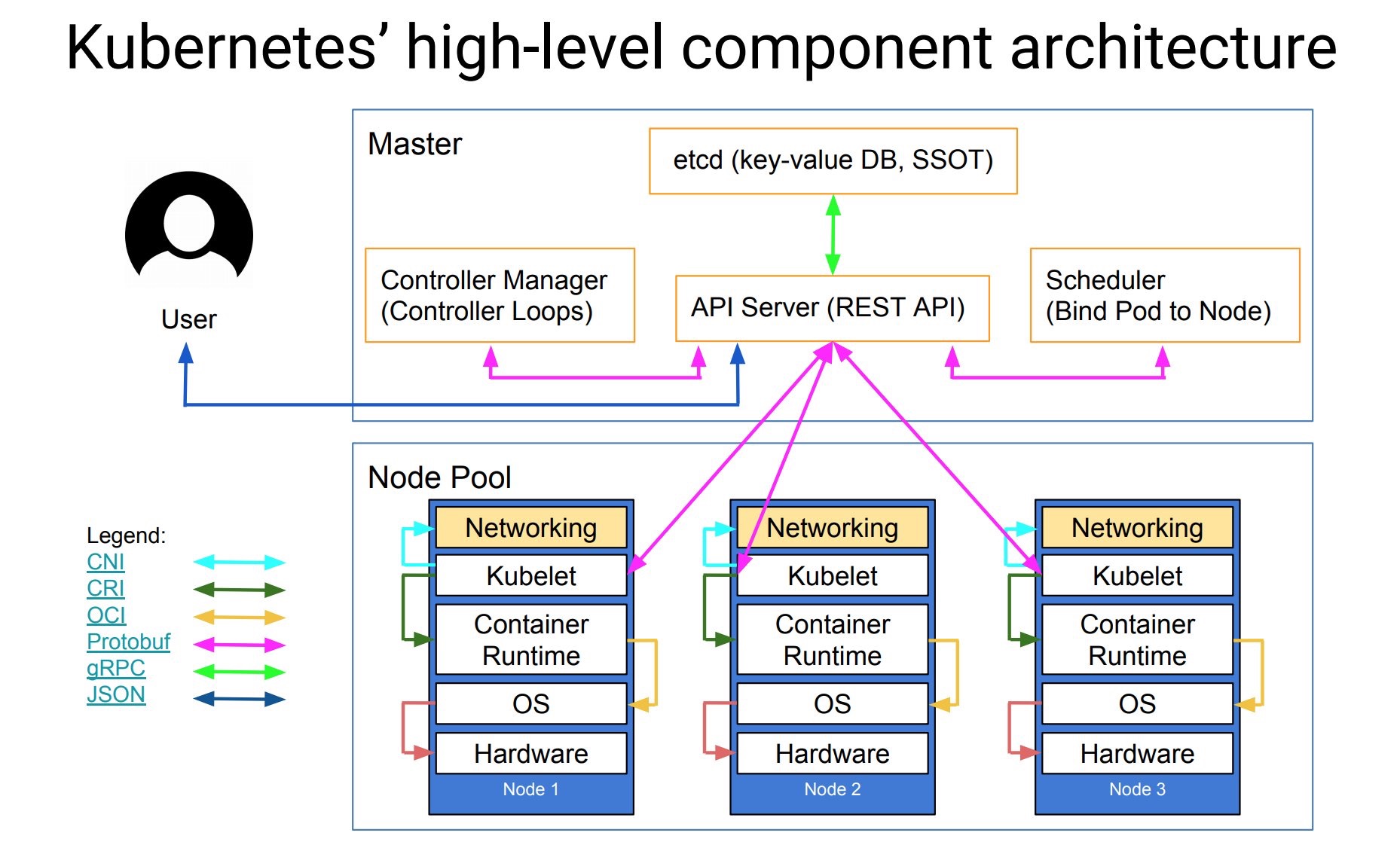
  • a more general abstract object. e.g. pod, service/svc, deployment, secret, namespace/ns, role e.t.c.

  • more DevOps engineering

previously, I palyed with k8s in theory. this time is more about build a k8s cluster in reality.

install kubeadm

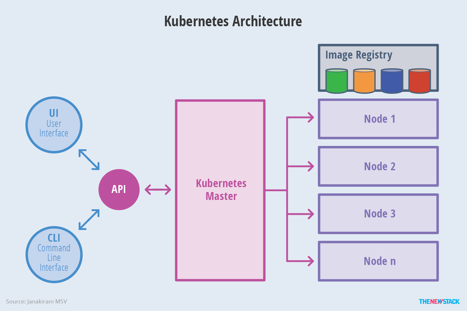
  • kubeadm, used to initial cluster

  • kubectl, the CLI tool for k8s

  • kubelet, run on all nodes in the cluster

all three commands are required on all nodes. check install kube officially

  • swapoff
1
sudo swapoff -a
  • create a file /etc/apt/sources.list.d/kubernetes.list with the following content:
1
deb https://mirrors.aliyun.com/kubernetes/apt/ kubernetes-xenial main
  • add gpg key
1
2
gpg --keyserver keyserver.ubuntu.com --recv-keys BA07F4FB
gpg --export --armor BA07F4FB | sudo apt-key add -
  • apt install
1
2
sudo apt-get update
sudo apt-get install kubelet kubectl kubeadm

tips, apt-get install will install v1.18.2.

  • restart kubelet
1
2
systemctl daemon-reload
systemctl restart kubelet

if need degrade to v17.3, do the following:

1
2
3
sudo apt-get install -qy --allow-downgrades kubelet=1.17.3-00
sudo apt-get install -qy --allow-downgrades kubeadm=1.17.3-00
sudo apt-get install -qy --allow-downgrades kubectl=1.17.3-00

kubeadm setup

we setup k8s with kubeadm tool, which requires a list of images:

  • check the required images to start kubeadm
1
kubeadm config images list

which returns:

1
2
3
4
5
6
7
k8s.gcr.io/kube-apiserver:v1.18.2
k8s.gcr.io/kube-controller-manager:v1.18.2
k8s.gcr.io/kube-scheduler:v1.18.2
k8s.gcr.io/kube-proxy:v1.18.2
k8s.gcr.io/pause:3.2
k8s.gcr.io/etcd:3.4.3-0
k8s.gcr.io/coredns:1.6.7

the image source above is not aviable, which can be solved by:

1
kubeadm config images pull --image-repository=registry.cn-hangzhou.aliyuncs.com/google_containers/

if the command above doesn’t work well, try to docker pull directly and tag the name back to k8s.gcr.io:

1
2
docker pull registry.cn-hangzhou.aliyuncs.com/google_containers/$imageName
docker tag registry.cn-hangzhou.aliyuncs.com/google_containers/$imageName k8s.gcr.io/$imageName

start a k8s cluster

after the preparation above, finally start a k8s cluster as:

1
kubeadm init --pod-network-cidr=10.4.0.0/16 --cluster_dns=10.3.0.10

futher, check kubeadm init options:

1
2
3
4
5
--pod-network-cidr # pod network IP range
--service-cidr # default 10.96.0.0/12
--service-dns-domain #cluster.local

cluster_dns option is used as the cluster DNS/namespace, which will be used in the configureMap for coreDNS forwarding.

if start successfully,

  • then run the following as a regular user to config safety-verficiation:
1
2
3
mkdir -p $HOME/.kube
sudo cp -i /etc/kubernetes/admin.conf $HOME/.kube/config
sudo chown $(id -u):$(id -g) $HOME/.kube/config
  • check
1
2
3
sudo kubectl get nodes #both nodes are READY
sudo kubectl get pods -n kube-system #check system
sudo kubectl describe pod coredns-xxxx -n kube-system

add pod network

pod network, is the network through which the cluster nodes can communicate with each other.

1
sudo kubectl apply -f https://raw.githubusercontent.com/coreos/flannel/master/Documentation/kube-flannel.yml
  • worker node to join the new k8s cluster :
1
2
3
4
kubeadm reset
sudo swapoff -a
kubeadm join 10.20.180.12:6443 --token o0pcpc.v3v8bafmbu6e4bcs \
--discovery-token-ca-cert-hash sha256:2a15d392821f8c51416e49e6ccd5393df6f93d738b24b2132e9a9a19276f4f54

then cp flannel-cni.conflist into worker node. /etc/cni/net.d/10-flannel.conflist to the same path in worker node.

if check sudo kubectl get pods -n kube-system : there may come an error: here found: coredns CrashLoopBackOff or Error

this is due to DNS/nameserver resolving issue in Ubuntu, wherecoreDNS serviceforwarding the k8s cluster service to the host/etc/resolv.conf, which only has127.0.0.1`. the cause for CoreDNS to have CrashLoopBackOff is when a CoreDNS Pod deployed in Kubernetes detects a loop. A number of workarounds are available to avoid Kubernetes trying to restart the CoreDNS Pod every time CoreDNS detects the loop and exits.

check the coreDNS configMap by :

1
kubectl edit cm coredns -n kube-system

we see something like:

1
2
3
4
5
6
7
prometheus :9153
# forward . /etc/resolv.conf
forward . 10.3.0.10
cache 30
loop
reload
loadbalance

so modify forward line to forward . 10.3.0.10. or to delete loop service there, which is not good idea.

a very good explain

test cluster

test sample

clear cluster

clear test

1
sudo systemctl stop kubelet kube-proxy flanneld docker

understand CNI (container network interface)

the following network plugin can be found from k8s cluster networking

  • backgroud

container network is used to connect (container itself) to other containers, host machine or external network. container in runtime has a few network mode:

1
2
3
4
5
none
host
bridge

CNI brings a general network framework, used to manage network configure and network resources.

coreDNS

first, run coreDNS as a service in the cluster. then, update kubelet parameters to include IP of coreDNS and the cluster domain.

if there is no existing running Kube-DNS, or need a different CLusterIP for CoreDNS, then need update kubelet configuration to set cluster_dns and cluster_domain appropriately, which can be modified at:

/etc/systemd/system/kubelet.service/10-kubeadm.conf with additional options appending at kubelet line :

1
--cluster_dns=10.3.0.10 --cluster_domain=cluster.local
  • restart kubelet service
1
2
3
systemctl status kubelet
systemctl daemon-reload
systemctl restart docker

flannel mis-usage

in the settings above, I manually copy flannel-cni.conflist and /run/flannel/subnet.env to worker node every time, whenever reboot the worker node. if else, the cluster bother the worker node is NotReady. as we deploy the cluster with kubectl, which is kind of a swarm service deploy tool. so the right way to use flannel should have all k8s.gcr.io/kube-proxy, quay.io/coreos/flannel images at worker node as well.

for version1.17+, flannel replace the default kube-proxy, but it still requires to have kube-proxy running in each node(kubelet).

after restart kubelet, checking pods -n kube-system, it shows kube-proxy and flannel on each node has a Running status. coreDNS services has run the same size of copies as the number of nodes, but we can find that all of them are running on leader node.

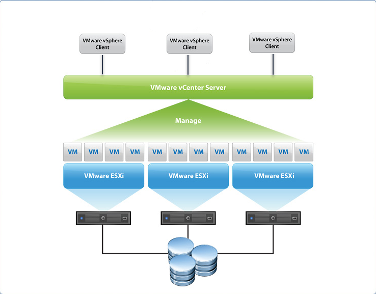
understand pod in k8s

accessing k8s pods from outside of cluster

  • hostNetwork: true

this option applies to k8s pods, which work as --network=host in docker env.

options can used for create pod: name command args env resources ports stdin tty

create pod/deployment using yaml

k8s task1: define a command and args for a container

templating YAML in k8s with real code

but hostNetwork is only yaml supported

  • hostPort

the container port is exposed to the external network at :.

1
2
3
4
5
spec:
containers:
ports:
- containerPort: 8086
hostPort: 8086

hostPort allows to expose a single container port on the hostIP. but the hostIP is dynamic when container restarted

  • nodePort

by default, services are accessible at ClusterIP, which is an internal IP address reachable from inside the cluster. to make the service accessible from outside of the cluster, can create a NodePort type service.

once this service is created, the kube-proxy, which runs on each node of the cluster, and listens on all network interfaces is instructed to accept connections on port 30000, (from any IP ?). the incoming traffc is forwardedby the kube-proxy to the selected pods in a round-robin fashion.

this service represents a static endpoint through which the selected pods can be reached.

  • Ingress

The Ingress controller is deployed as a Docker container on top of Kubernetes. Its Docker image contains a load balancer like nginx or HAProxy and a controller daemon.

view pods and nodes

  • check running pods on which node

resolv.conf in k8s pod

run as interactive into a k8s pod, then check its resolv.conf:

1
2
3
nameserver 10.96.0.10
search default.svc.cluster.local svc.cluster.local cluster.local
options ndots:5

10.96.0.10 is the K8S DNS server IP, which is actually the service IP of kube-dns service.

interesting, we can ping neither 10.96.0.10, nor 10.4.0.10, which is not existing service in the cluster, nor 10.3.0.10, which is the coreDNS forwarding IP.

remember during setup the k8s cluster, we had define the coreDNS forwarding to 10.3.0.10, is this why I can’t run curl http://<ip>:<port> works ?

check coreDNS service:

1
2
3
4
5
kubectl describe pods coredns-66bff467f8-59g97 -n kube-system
Name: coredns-66bff467f8-59g97
Node: meng/10.20.180.12
Labels: k8s-app=kube-dns
IP: 10.4.0.6

when start coreDNS, is actually used to relace kube-dns.

understand service in k8s

doc

Each Pod gets its own IP address, however in a Deployment, the set of Pods running in one moment in time could be different from the set of Pods running that application a moment later.

A Service in Kubernetes is a REST object, similar to a Pod. you can POST a Service definition to the API server to create a new instance.

Kubernetes assigns this Service an IP address, sometimes called the clusterIP,

Virtual IP and service proxies

Every node in a Kubernetes cluster runs a kube-proxy, kube-proxy is responsible for implementing a form of virtual IP for Services, whose is type is any but not ExternalName.

choosing own IP for service

You can specify your own cluster IP address as part of a Service creation request. The IP address that you choose must be a valid IPv4 or IPv6 address from within the service-cluster-ip-range CIDR range that is configured for the API server

discovering services

  • ENV variables

  • DNS

headless services

by explicitly specifying “None” for the cluster IP (.spec.clusterIP).

publishing services(ServiceTypes)

expose a service to an external IP address, outside of the cluster.

service has four type:

  • ClusterIP (default): expose the service on a cluster-internal IP, which is only reachable inside the cluster

  • NodePort: expose the service on each node’s IP at a static port(NodePort), to access : :

  • ExternalName: map the services to an externalName

  • LoadBalancer: expose the service externally using third-party load balancer(googl cloud, AWS, kubeadm has none LB)

NodePort and LoadBalancer can expose service to public, or outside of the cluster.

external IPs

if there are external IPs that route to one or more cluster nodes, services can be exposed on those externalIPs.

yaml deployment of service/pod

the previous sample busybox, is running as pod, through kubectl run busybox ? so there is no external

  • deployment obj
  • using yaml file to create service and expose to public
    some basic knowledge:

1) pod is like container in docker, which assigned a dynamic IP in runtime, but this pod IP is only visible inside cluster

2) service is an abstract concept of pod, which has an unique exposed IP, and the running pods belong to this service are managed hidden.

  • pod or deployment or service

both pod and deployment are full-fledged objects in k8s API. deployment manages creating Pods by means of ReplicaSets, namely create pods with spec taken from the template. since it’s rather unlikely to create pods directly in a production env.

in production, you will almost never use an object with the type pod. but a deployment object, which needs to keep the replicas(pod) alive. what’s use in practice are:

1) Deployment object, where to specify app containers with some specifications

2) service object

you need service object since pods from deployment object can be killed, scaled up and down, their IP address is not persistent.

kubectrl commands

1
2
3
4
5
6
7
8
9
10
11
12
13
14
15
16
17
18
19
20
21
22
23
24
25
26
27
kubectl get [pods|nodes|namespaces|services|pv] --ns your_namespace
kubectl describe [pods|nodes|namespaces]
kubectl label pods your_pod new-label=your_label
kubectl apply -f [.yaml|.json] #creates and updates resources in the cluster
kubectl create deployment service_name --imae=service_image #start a single instance of service
kubectl rollout history deployment/your_service #check history of deployment
kubectl expose rc your_sevice --port=80 --target-port=8000
kubectl autoscale deployment your_service --min=MIN_Num --max=MAX_Num
kubectl edit your_service #edit any API resource in your preferred editor
kubectl scale --replicas=3 your_service
kubectl delete [pod|service]
kubectl logs your_pod # dump pod logs
kubectl run -i --tty busybox --image=busybox -- sh # run pod as interactive shell
kubectl exec -ti your_pod -- ls | nslookup kubernetes.default #run command in existing pod (1 container case)

kubectl is pretty much like docker command and more.

refere

blog: setup k8s on 3 ubuntu nodes

cni readme

flannel for k8s from silenceper

coreDNS for k8s service discovery

services deploy in docker swarm

Posted on 2020-04-28 |

backgroud

our application so far includes the following three services:

  • simulator

  • pythonAPI

  • redisJQ

docker swarm network has the following three kind of networks, of course bridge to host network.

  • overlay network, services in the same overlay network, can communicate to each other

  • routing network, the service requested can be hosted in any of the running nodes, further as load balancer.

  • host network

usually, multi-container apps can be deployed with docker-compose.yml, check docker compse for more details.

DNS service discovery

the following is an example from (overlay networking and service discovery:

my test env includes 2 nodes, with host IP as following. when running docker services, it will generate a responding virtual IP, while which is dynamic assgined.

hostname virtualIP hostIP
node1 10.0.0.4 xx.20.181.132
node2 10.0.0.2 xx.20.180.212

a common issue when try first to use overlay network in swarm, e.g. ping the other service doesn’t work, check /etc/resolv.conf file:

1
2
3
4
5
6
7
8
9
10
11
12
13
14
15
16
# cat /etc/resolv.conf
nameserver 8.8.8.8
nameserver 8.8.4.4
```
the default `dns=8.8.8.8` can't ping either hostIP or any docker0 IP. the reason can find [#moby/#23910](https://github.com/moby/moby/issues/23910): When spinning up a container, Docker will by default check for a DNS server defined in /etc/resolv.conf in the host OS, and if it doesn't find one, or finds only 127.0.0.1, will opt to use Google's public DNS server 8.8.8.8.
one solution mentioned:
* cat /etc/docker/daemon.json
```xml
{
"dns": ["172.17.0.1", "your.dns.server.ip", "8.8.8.8"]
}
  • add a file /etc/NetworkManager/dnsmasq.d/docker-bridge.conf
1
listen-address=172.17.0.1

so basically, the default DNS setting only listens to DNS requests from 127.0.0.1 (ie, your computer). by adding listen-address=172.17.0.1, it tells it to listen to the docker bridge also. very importantly, Docker DNS server is used only for the user created networks, so need create a new docker network. if use the default ingress overlay network, the dns setup above still doesn’t work.

another solution is using host network, mentioned using host DNS in docker container with Ubuntu

test virtualIP network

  • create a new docker network
1
docker network create -d overlay l3

why here need a new network ? due to Docker DNS server(172.17.0.1) is used only for the user created networks

  • start the service with the created network:
1
2
3
4
5
6
7
docker service create --name lg --replicas 2 --network l3 20.20.180.212:5000/lg
```
* check vip on both nodes
```sh
docker network inspect l3

check vip by the line IPv4Address:

1
2
node1 vip : `10.0.1.5/24`
node2 vip: `10.0.1.6/24`
  • go to the running container
1
2
3
4
docker exec -it 788e667ea9cb /bin/bash
apt-get update && apt-get install iputils-ping
ping 10.0.1.5
ping 10.0.1.6
  • now ping service-name directly
1
2
ping lg
PING lg (10.0.1.2) 56(84) bytes of data.
  • inspect service
1
2
3
4
5
6
docker service inspect lg
"VirtualIPs": [
{
"Addr": "10.0.1.2/24"
}
]
  • ping host IP from contianer vip

as far as we add both host dns and docker0 dns to the dns option in /etc/docker/daemon.json, the container vip can ping host IP.

assign ENV variable from script

  • get services vip

get vip list

1
2
vip=`sudo docker service inspect --format '{{.Endpoint.VirtualIPs}}' lgsvl | awk '{print substr($2, 1, length($2)-5)}'`
echo $vip
  • create docker service with runtime env
1
2
3
4
5
6
7
8
9
10
11
12
ping -c 1 lg | awk 'NR==1 {print $2}'
```
## multi-services test
#### run all services in single docker mode
```sh
docker run -it -p 6379:6379 --mount source=jq-vol,target=/job_queue redisjq /bin/bash
docker run xx.xx.xx.xxx:5000/lg
docker run -it --mount source=jq-vol,target=/pythonAPI/job_queue xx.xx.xx.xxx:5000/redispythonapi /bin/bash
  • check docker-IP of lg :
1
2
docker sh
docker container inspect <lg> #get its IP-address
  • update SIMULATOR_HOST for redispythonapi
1
2
3
docker exec -it <redispythonapi> /bin/bash
export SIMULATOR_HOST=lg_ip_address #from the step above
./redis_worker.sh #where all python scenarios are running in queue

here we can check the lg container’s IP is 172.17.0.3 and redispythonapi’s IP is 172.17.0.4, then update start_redis_worker.sh with SIMULATOR_HOST=172.17.0.3

  • get the container IP
1
2
docker container ls | grep -w xx.xx.xx.xxx:5000/lg | awk '{print $1}'
docker inspect --format='{{range .NetworkSettings.Networks}}{{.IPAddress}}{{end}}' $(docker container ls | grep -w xx.xx.xx.xxx:5000/lg | awk '{print $1}' )

assign a special IP to service in swarm

docker network create support subnet, which only ip-addressing function, namely we can use custom-defined virtual IP for our services. a sample:

1
2
3
4
5
6
7
8
9
10
11
12
13
14
15
16
17
docker network create -d overlay \
--subnet=192.168.10.0/25 \
--subnet=192.168.20.0/25 \
--gateway=192.168.10.100 \
--gateway=192.168.20.100 \
--aux-address="my-router=192.168.10.5" --aux-address="my-switch=192.168.10.6" \
--aux-address="my-printer=192.168.20.5" --aux-address="my-nas=192.168.20.6" \
my-multihost-network
```
we can run our application as:
```sh
docker network create --driver=overlay --subnet=192.168.10.0/28 lgsvl-net
docker service create --name lgsvl --replicas 2 --network lgsvl-net --host "host:192.168.10.2" xx.xx.xx.xxx:5000/lgsvl
docker service create --name redis --replicas 1 --network lgsvl-net -p 6379:6379 --mount source=jq-vol,target=/job_queue --constraint 'node.hostname==ubuntu' xx.xx.xx.xxx:5000/redisjq
docker service create --name pythonapi --replicas 1 --network lgsvl-net --mount source=jq-vol,target=/pythonAPI/job_queue xx.xx.xx.xxx:5000/redispythonapi

understand subnet mask. IP address include master IP and subnet mask, we choose 28 here, basically generate about 2^(32-28)-2= 14 avaiable IP address in the subnet. but in a swarm env, subnet IPs are consuming more as the nodes or replicas of service increase.

taking an example, with 2-nodes and 2-replicas of service, 5 subnet IPs are occupied, rather than 2

run docker network inspect lgsvl-net on both nodes:

  • on node1 gives:
1
2
lg.1 IPV4Address: 192.168.10.11/28
lgssvl-net-endpoint: 192.168.10.6/28
  • on node2 gives:
1
2
3
4
5
6
7
8
lg.2 IPV4Address: 192.168.10.4/28
lgssvl-net-endpoint: 192.168.10.3/28
```
* `docker service inspect lg` gives:
```xml
VirualIPs: 192.168.10.2/28

clearly 5 IP address are occupied. and the IP for each internal service is random picked, there is no gurantee service will always get the first avaiable IP.

docker serivce with –ip

only docker run –ip works, there is no similar --ip option in docker service create. but a lot case require this feature: how to publish a service port to a specific IP address, when publishing a port using --publish, the port is published to 0.0.0.0 instead of a specific interface’s assigned IP. and there is no way to assign an fixed IP to a service in swarm.

a few disscussion in moby/#26696, add more options to `service create, a possible solution, Static/Reserved IP addresses for swarm services

mostly depend on the issues like “ip address is not known in advance, since docker service launched in swarm mode will end up on multiple docker servers”. there should not be applicable to docker swarm setup, since if one decides to go with docker swarm service, has to accept that service will run on multiple hosts with different ip addresses. I.e. trying to attach service / service instance to specific IP address somewhat contradicting with docker swarm service concept.

docker service create does have options --host host:ip-address and --hostname and similar in docker service update support host-add and host-rm.

1
2
3
4
5
6
7
8
9
10
11
12
13
14
$ docker service create --name redis --host "redishost:192.168.10.2" --hostname myredis redis:3.0.6
```
then exec into the running container, we can check out `192.168.10.2 redishost` is one line in `/etc/hosts` and `myredis` is in `/etc/hostname`
but remember, the DNS for this hostIP(192.168.10.2) should be first configured in the docker engine DNS list. if not, even the hostIP is in the arrange of the subnet, it is unreachable from the containers.
[another explain](https://www.freecodecamp.org/news/docker-nginx-letsencrypt-easy-secure-reverse-proxy-40165ba3aee2/): by default docker containers are put on their own network. This means that you won’t be able to access your container by it’s hostname, if you’re sitting on your laptop on your host network. It is only the containers that are able to access each other through their hostname.
#### dnsrr vs vip
```sh
--endpoint-mode dnsrr

dnsrr mode, namely DNS round Robin mode, when query Docker’s internal DNS server to get the IP address of the service, it will return IP address of every node running the service.

vip mode, return the IP address of only one of the running cntainers.

When you submit a DNS query for a service name to the Swarm DNS service, it will return one, or all, the IP addresses of the related containers, depending on the endpoint-mode.

dnsrr vs vip: Swarm defaults to use a virtual ip (endpoint-mode vip). So each service gets its own IP address, and the swarm load balancer assigns the request as it sees fit; to prevent a service from having an IP address, you can run docker service update your_app --endpoint-mode dnsrr, which will allow an internal load balancer to run a DNS query against a service name, to discover each task/container’s IP for a given service

in our case, we want to assign a speical IP to the service in swarm. why? because our app has websocket server/client communicataion, which is IP address based. we can’ assign service name for WS server/client.

check another issue: dockerlize a websocket server

global mode to run swarm

when deploying service with global mode, namely each node will only run one replicas of the service. the benefit of global mode is we can always find the node IP, no matter the IP address is in host network or user-defined overlay network/subnetwork.

get service’s IP in global mode

get listened port

1
2
3
4
root@c7279faebefa:/lgsvl# netstat -tulpn | grep LISTEN
tcp 0 0 127.0.0.11:33263 0.0.0.0:* LISTEN -
tcp 0 0 0.0.0.0:8080 0.0.0.0:* LISTEN 7/lgsvl_Core.x86_64
tcp 0 0 0.0.0.0:8181 0.0.0.0:* LISTEN 7/lgsvl_Core.x86_64

both 8080 and 8181 is listening after lgsvl service started. on the lgsvl side, we can modify it to listen on all address with 8181 port. then the following python script to find node’s IP:

1
2
3
4
5
6
7
8
9
10
11
import socket
def get_host_ip():
try:
s = socket.socket(socket.AF_INET, socket.SOCK_DGRAM)
s.connect(('8.8.8.8', 80))
ip = s.getsockname()[0]
finally:
s.close()
return ip

in this way, no need to pre-define the SIMULATOR_HOST env variable at first. the pythonAPI only need to find out its own IP and detect if 8181 is listening on in runtime.

container vs service

difference between service and container:

  • docker run is used to create a standalone container

  • docker service is the one run in a distributed env. when create a service, you specify which container image to use and which commands to execue inside the running containers.

There is only one command(no matter the format is CMD ENTRYPOINT or command in docker-compose) that docker will run to start your container, and when that command exits, the container exits. in swarm service mode, with default restart option(any), the container run and exit and restart again with a different containeID. check dockerfile, docker-compose and swarm mode lifecycle for details.

docker container restart policy:

docker official doc: start containers automatically

  • no, simply doesn’t restart under any circumstance

  • on-failure, to restart if the exit code has error. user can specify a maximum number of times Docker will automatically restart the container; the container will not restart when app exit with a successful exit code.

  • unless-stopped, only stop when Docker is stopped. so most time, this policy work exactly like always, one exception, when a container is stopped and the server is reboot or the DOcker serivce is restarted, the container won’t restart itself. if the container was running before the reboot, the container would be restarted once the system restarted.

  • always, tells Docker to restart the container under any circumstance. and the service will restart even with reboot. any other policy can’t restart when system reboot.

similar restart policy can be found in :

  • docker-compose restart policy
  • docker service create restat-condition

keep redisJQ alive in python script

by default setup, redis server is keep restarting and running, which make the pythonapi service always report: redis.exceptions.ConnectionError: Error 111 connecting to xx.xxx.xxx:6379. Connection refused.

so we can keep redisJQ alive in python script level by simply a while loop.

for test purpose, we also make pythonAPI restart policy as none, so the service won’t automatically run even with empty jobQueue.

the final test script can run in the following:

1
2
3
docker service create --name lgsvl --network lgsvl-net --mode global xx.xx.xx.xxx:5000/lgsvl
docker service create --name redis -p 6379:6379 --network lgsvl-net --mount source=jq-vol,target=/job_queue --constraint 'node.hostname==ubuntu' xx.xx.xx.xxx:5000/redisjq
docker service create --name pythonapi --network lgsvl-net --mode global --mount source=jq-vol,target=/pythonAPI/job_queue --restart-condition none xx.xx.xx.xxx:5000/pythonapi

use python variable in os.system

sample

1
os.system("ls -lt %s"%your_py_variable)

proxy in docker swarm

HAProxy

Routing external traffic into the cluster, load balancing across replicas, and DNS service discovery are a few capabilities that require finesse. but proxy can’t either assign a special IP to a special service, neither can expose the service with a fixed IP, so in our case, no helpful.

redis task queue (2)

Posted on 2020-04-28 |

background

currently, we add job_queue list inside Dockerfile by COPY the job_queue folder from local host to the docker image, which is not dynamically well, and can’t support additionaly scenarios.

to design a redisJQ service that can used in swarm/k8s env, need consider DNS to make the servie available and shared volume to share the data in job queue to other services.

ceph rbd driver for docker

ceph can store files in three ways:

  • rbd, block storage, which usually used with virtualization kvm

  • object storage, through radosgw api, or access by boto3 APIs.

  • cephfs, mount ceph as file system

the first idea is from local host mount to remote volume(e.g. ceph storage) mount. there are a few popular rbd-drive plugins:

  • Yp engineering

  • AcalephStorage

  • Volplugin

  • rexray.io

check ceph rbd driver to understand more details.

to support rbd-driver plugin in docker, the ceph server also need support block device driver, which sometime is not avaiable, as most small ceph team would support one or another type, either objec storage or block storage. and that’s our situation. so we can’t go with rbd-driver plugin.

another way is to use docker volume cephfs, similar reason our ceph team doesn’t support cephfs.

ceph object storage access

as the ceph team can support boto3 API to access ceph, which gives us the one and only way to access scenarios: boto3.

basically the redis_JQ first download all scenaio files from remote ceph through boto3 APIs, then scan the downloaded files into JQ, then feed into the python executors in front.

s3 client

  • aws cli
1
2
3
4
curl "https://awscli.amazonaws.com/awscli-exe-linux-x86_64.zip" -o "awscliv2.zip"
unzip awscliv2.zip
sudo ./aws/install
/usr/local/bin/aws --version
  • s3cmd

access files in folders in s3 bucket

1
2
3
4
5
6
7
8
9
10
def download_files(self, bucket_name, folder_name):
files_with_prefix = self.s3_client.list_objects_v2(Bucket=bucket_name, Prefix=folder_name)
scenario_basename = "/pythonAPI/job_queue/scenario"
i = 0
for file_ in files_with_prefix["Contents"]:
scenario_name = scenario_basename + "%d"%i + ".py"
print(scenario_name)
self.download_file(bucket_name, file_['Key'], scenario_name, False)
time.sleep(0.01)
i += 1

manage python modules

during the project, we really need take care python packages installed by apt-get, pip and conda, if not there will conflicts among different version of modules:

1
2
3
4
import websockets
Trackbac:
File "/usr/lib/python3/dist-packages/websockets/compatibility.py", line 8
asyncio_ensure_future = asyncio.async # Python < 3.5

so it’s better to use conda or python virtual-env to separate the different running envs. and install packages by conda install is better choice, than the global apt-get install:

  • conda install ws

  • conda install pandas

  • conda install asammdf

  • conda install botocore

  • conda install sqlalchemy

  • conda install websocket-client

  • conda install redis

  • conda install boto3

basic of python import

  • module, any *.py file, where its name is the file name

  • package, any folder containing a file named __init__.py in i, its name is the name of the folder.

When a module named module1 is imported, the interpreter first searches for a built-in module with that name. If not found, it then searches for a file named module1.py or a folder named module1 in a list of directories given by the variable sys.path

sys.path is initialized from 3 locations:

  • the directory containing the input script, or the current directory

  • PYTHONPATH

  • the installation-dependent default

if using export PYTHONPATH directly, it works. but once defined in ~/.bashrc it doesn’t actually triggered in conda env.
it simpler to add the root directory of the project to the PYTHONPATH environment variable and then running all the scripts from that directory’s level and changing the import statements accordingly. import search for your packages in specific places, listed in sys.path. and The current directory is always appended to this list

redis service

the common error: redis.exceptions.ConnectionError: Error 111 connecting to 10.20.181.132:6379. Connection refused. , which basically means the system can’t connect to redis server, due to by default redis only allow localhost to access. so we need configure non-localhost IP to access redis db.

  • check redis-server running status
1
2
3
ps aux | grep redis-server
netstat -tunple | grep 6379
redis-cli info
  • shutdown redis-server
1
sudo kill -9 $pid

redis-server & redis-cli

redis-server start redis server with a default config file at /etc/redis/redis.config

a few item in the configure file need take care:

  • bind, check here

the default setting is to bind 127.0.0.1,which means redis db is stored and only can be access through localhost. for our case, to allow hostIP(10.20.181.132), or even any IP to access, need :

1
bind 0.0.0.0
  • redislog, default place at /var/log/redis/redis-server.log
  • requirepass, for security issues, please consider this item

  • login client with hostIP

1
redis-cli -h 10.20.181.132
  • basic operation of redis-cli

log in redis-cli first, then run the following:

1
2
3
4
LPUSH your_list_name item1
LPUSH your_list_name item2
LLEN your_list_name
EXISTS your_list_name

redis service in docker

the following is an example from create a redis service

  • connect to the redis container directly
1
docker run -it redis-image /usr/bin/redis-server /etc/redis/myconfig.conf

in this way, redis service will use its docker VIP, which can be checked from:

1
2
docker ps
docker inspect <container_id>

which will give somehing like:

1
2
3
"bridge": {
"Gateway": "172.17.0.1",
"IPAddress": "172.17.0.2",

then the redis-server can connect by:

1
redis-cli -h 172.17.0.2
  • connect to the host os
1
docker run -it -p 6379 redis-image /usr/bin/redis-server /etc/redis/myconfig.conf

the redis container has exported 6379, which may map to another port on host os, check:

1
2
3
docker ps
docker port <container_id> 6379 #gives the <exernal_port> on host
rdis-cli -h 10.20.181.132 -p <external_port>
  • run redis service with host network
1
docker run -it --network=host redis-image /usr/bin/redis-server /etc/redis/myconfig.conf

in this way, there is no bridge network, or docker VIP. the host IP and port is directly used. so the following works

1
redis-cli -h 10.20.181.132 -p 6379

A good way now, is to map host redis_port to container redis_port, and use the second way to access redis.

1
docker run -it -p 6379:6379 redisjq /bin/bash

tips, need to confirm 6379 port at host machine is free.

share volumes among multi volumes

the problem is redisjq service download all scenarios scripts in its own docker container, and only store the scenario name in redis db. when redis_worker access the db, there is no real python scripts. so need to share this job-queue to all redis_workers

mount volume

1
docker run -it -p 6379:6379 --mount source=jq-vol,target=/job_queue redisjq /bin/bash

start pythonapi to access the shared volume

1
docker run -it --mount source=jq-vol,target=/pythonAPI/job_queue redispythonapi /bin/bash

refer

qemu/kvm & ceph: rbd drver in qemu

基于 Ceph RBD 实现 Docker 集群的分布式存储

rexray/rbd 参考

access cephFS inside docker container without mounting cephFS in host

how to use folders in s3 bucket

the definitive guide to python import statements

play with k8s

Posted on 2020-04-09 |

basic k8s

kubeadm init

init options can be:

  • --apiserver-bind-port int32, by default, port=6443

  • --config string, can pass in a kubeadm.config file to create a kube master node

  • --node-name string, attach node name

  • --pod-network-cidr string, used to set the IP address range for all Pods.

  • --service-cide string, set service CIDRs, default value is 10.96.0.0/12

  • --service-dns-domain string, default value is cluster.local

  • --apiserver-advertise-address string, the broadcast listened address by API Server

nodes components

IP hostname components
192.168.0.1 master kube-apiserver, kube-controller-manager, kube-scheduler, etcd, kubelet, docker, flannel, dashboard
192.168.0.2 worker kubelet, docker, flannel

ApiServer

when first launch Kubelet, it will send the Bootstrapping request to kube-apiserver, which then verify the sent token is matched or not.

1
2
3
4
5
6
7
8
9
10
--advertise-address = ${master_ip}
--bind-address = ${master_ip} #can't be 127.0.0.1
--insecure-bind-address = ${master_ip}
--token-auth-file = /etc/kubernets/token.csv
--service-node-port-range=${NODE_PORT_RANGE}

how to configure master node

cluster IP

it’s the service IP, which is internal, usually expose the service name.

the cluse IP default values as following:

1
2
--service-cluster-ip-range=10.254.0.0/16
--service-node-port-range=30000-32767

k8s in practice

image

image

image

blueKing is a k8s solution from TenCent. here is a quickstart:

  • create a task

  • add agnet for the task

  • run the task & check the sys log

  • create task pipeline (CI/CD)

create a new service in k8s

  • create namespace for speical bussiness
  • create serivces, pull images from private registry hub
1
2
kubectl create -f my-nginx-2.yaml
kubctl get pods -o wide

how external access to k8s pod service ?

pod has itw own special IP and a lifecyle period. once the node shutdown, the controller manager can transfer the pod to another node. when multi pods, provides the same service for front-end users, the front end users doesn’t care which pod is exactaly running, then here is the concept of service:

service is an abstraction which defines a logical set of Pods and a policy by which to access them

service can be defined by yaml, json, the target pod can be define by LabelSeletor. a few ways to expose service:

  • ClusterIP, which is the default way, which only works inside k8s cluster

  • NodePort, which use NAT to provide external access through a special port, the port should be among 8400~9000. then in this way, no matter where exactly the pod is running on, when access *.portID, we can get the serivce.

  • LoadBalancer

1
2
3
kubectl get services
kubectl expose your_service --type="NodePort" --port 8889
kubctl describe your_service

use persistent volume

  • access external sql

  • use volume

volume is for persistent, k8s volume is similar like docker volume, working as dictory, when mount a volume to a pod, all containers in that pod can access that volume.

  • EmptyDir
  • hostPath
  • external storage service(aws, azure), k8s can directly use cloud storage as volume, or distributed storage system(ceph):

sample

1
2
3
4
5
6
7
8
9
10
11
12
13
14
15
16
17
18
19
20
21
22
23
24
25
26
27
28
29
30
31
apiVersion: v1
kind: Pod
metadata:
name: using-ebs
metadata:
name: using-ceph
spec:
containers:
-image: busybox1
name: using-ebs
volumeMounts:
-mountPath: /test-ebs
name: ebs-volume
-image: busybox2
name: using-ceph
volumeMounts:
-name: ceph-volume
mountPath: /test-ceph
volumes:
-name: ebs-volume
awsElasticBlockStore:
volumeID: <volume_id>
fsType: ext4
-name: ceph-volume
cephfs:
path: /path/in/ceph
monitors: "10.20.181.112:6679"
secretFile: "/etc/ceph/admin/secret"

containers communication in same pod

first, containers in the same pod, the share same network namespace and same iPC namespace, and shared volumes.

  • shared volumes in a pod

when one container writes logs or other files to the shared directory, and the other container reads from the shared directory.

image

  • inter-process communication(IPC)

as they share the same IPC namespace, they can communicate with each other using standard ipc, e.g. POSIX shared memory, SystemV semaphores

image

  • inter-container network communication

containers in a pod are accessible via localhost, as they share the same network namespace. for externals, the observable host name is the pod’s name, as containers all have the same IP and port space, so need differnt ports for each container for incoming connections.

image

basically, the external incoming HTTP request to port 80 is forwarded to port 5000 on localhost, in pod, and which is not visiable to external.

how two services communicate

  • ads_runner
1
2
3
4
5
6
7
8
9
10
11
12
13
apiVersion: v1
kind: Service
metadata:
name: ads_runner
spec:
selector:
app: ads
tier: api
ports:
-protocol: TCP
port: 5000
nodePort: 30400
type: NodePort

if there is a need to autoscale the service, check
k8s autoscale based on the size of queue.

  • redis-job-queue
1
2
3
4
5
6
7
8
9
10
11
12
apiVersion: v1
kind: Service
metadata:
name: redis-job-queue
spec:
selector:
app: redis
tier: broker
ports:
-portocol: TCP
port: 6379
targetPort: [the port exposed by Redis pod]

ads_runner can reach Redis by address: redis-server:6379 in the k8s cluster.

redis replication has great async mechanism to support multi redis instance simutanously, when need scale the redis service, it is ok to start a few replicas of redis service as well.

redis work queue

check redis task queue:

  • start a storage service(redis) to hold the work queue
  • create a queu, and fill it with messages, each message represents one task to be done
  • start a job that works on tasks from the queue

refer

jimmysong

BlueKing configure manage DB

k8s: volumes and persistent storage

multi-container pods and container communication in k8s

k8s doc: communicate between containers in the same pod using a shared volume

kubeMQ: k8s message queue broker

3 types of cluster networking in k8s

redis task queue

Posted on 2020-04-09 |

background

redis is a in-memory database, like SQlite, but the other part of redis, is that it can use to write message queue for task scheduler.

job/task scheduler is a popular automatic tool used in cloud/HPC, when need to deal with lots of taskes/jobs.

for ADS simulation, a job scheduler can be used to manage the scenarios feed into the simulator. where the existing scenarios are stored as items in redis, and the redis server looks like a shared volume, which can be access by any worker services through redis_host. where simulator can enpacakged in a redis_worker.

redis

redis commands

redis is database, so there are plenty of commands used to do db operation. e.g.

1
2
3
4
5
6
GET, SET #string
HGET, HSET, #hash table
LPUSH, LPOP, BLPOP #list
SADD, SPOP, #set
PUBLISH, SUBSCRIBE, UNSUBSCRIBE, PUBSUB #pub&sub
...

redis in python

the following is from redis-py api reference

  • get/set string
1
2
3
r = redis.Redis(host='localhost', port=6379, db=0)
r.set('foo', 'bar')
r.get('foo')
  • connection pools

redis-py uses a connection pool to manage connections to a Redis server.

1
2
pool = redis.ConnectionPool(host='localhost', port=6379, db=0)
r = redis.Redis(connection_pool=pool)
  • connections

connectionPools manage a set of Connection instances. the default connection is a normal TCP socket based; also it can use UnixDomainSocketConnection, or customized protocol.

connection maintain an open socket to Redis server. when these sockets are disconnected, redis-py will raise a ConnectionError to the caller, also redis-py can issue regular health check to assess the liveliness of a connection.

  • parsers

parser provides the way to control how response from Redis server are parsed, redis-py has: PythonParser and the default HiredisParser.

  • response callbacks

the redis-py has its own client callbacks in RESPONSE_CALLBACKS. custom callbacks can add on per-instance using set_response_callback(command_name, callfn)

  • pub/sub

PubSub object can subscribes/unsubscribes to channels or patterns and listens for new messages.

1
2
3
4
5
6
r = redis.Redis(...)
p = r.pubsub()
p.subscribe('my-first-channel', ...)
p.psubscribe('my-first-patttern', ...)
p.unsubscribe('my-first-channel')
p.punsubscribe('my-first-pattern')

every message read from a PubSub instance will be a dict with following keys:

- type, e.g. subscribe, unsubscribe, psubscribe, message e.t.c
- channel
- pattern
- data

redis-py allows to register callback funs to handle published messages. these message handlers take a single argument the message. when a message is read with a message handler, the message is created and passed to the message handler:

1
2
3
4
5
6
def a_handler(message):
print message['data']
p.subscribe(**('my-channel': a_handler})
r.publish('my-channel', 'awesome handler')
p.get_message()
  • get_message()

get_message() use system’s select module to quickly poll the connection’s socket. if there’s data available to be read, get_message() will read it; if there’s no data to be read, get_message() will immediately return None:

1
2
3
4
5
while True:
message = p.get_message()
if message:
#do something with the message
time.sleep(0.01)
  • listen()

listen() is a generator(e.g. yield keyword), which blocks until a message is avaiable. if the app is ok to be blocked until next message avaiable, listen() is an easy way:

1
2
for message in p.listen():
#do something with the message
  • run_in_thread()

run an event loop in a separate thread. run_in_thread() returns a thread object, and it is simply a wrapper around get_message(), that runs in a separate thread, essentially creating a tiny non-blocking event loop. since it’s running in a separate thread, there is no way to handle message that aren’t automatically handled with registered message handlers.

1
2
3
4
p.subscribe(**{'my-channel': a_handler})
thread = p.run_in_thread(sleep_time = 0.01)
#when need shut down
thread.stop()

redis task queue in k8s

fine parallel processing using work queue is an good example of how to use redis as task queue.

first, fill the existing task lists into redis database(server) as a shared volume, then start mutli worker services to the shared volume to get the job to run.

design a data center for ADS applications

Posted on 2020-04-06 |

background

A system’s back end can be made up of a number of bare metal servers, data storage facilities, virtual machines, a security mechanism, and services, all built in conformance with a deployment model, and all together responsible for providing a service.

points to consider

  • it’s the primary authority and responsibility of the back end to provide a built-in security mechanism, traffic control and protocols.

  • a central server is responsible for managing and running the system, systematically reviewing the traffic and client request to make certain that everything is running smoothly.

service viewport

busniess services

the most common busniess services or application-as-a-service(aaas) in ADS data center includes:

  • massively scenario simualtion

  • open-loop re-play simulation

  • AI training

  • sensor data analysis

  • test driven algorithms dev

platform as a service

busniess services can be considered as the most abstract level services, paas consider how to support the upper level needs. a few components are obvious:

  • distributed data storage(aws s3, ceph)

  • massively data analysis(hadoop)

  • massively compute nodes(k8s/docker)

  • vdi server pool

  • sql

  • web server for end-user UI

IaaS

to support PaaS, we need CPUs, GPUs, network, either in physical mode or virtual mode. the common private cloud vendor would suggest a general virtualization layer, to manage all resources in one shot. but there is always an balance between the easy manage and performance lost.

for large auto industry OEMs, no doubt easy manage is crucial. so it’s suggested to implement virtual layer(either vmware or customized kvm). if not, I wonder the self-maintainaince will be a disaster in future.

security in cloud

who is Cybersecurity professional

the guy who provide security during the development stages of software systems, networks, and data centers.

must make security measures for any information by designing various defensive systems and strategies against intruders.

The specialist must create new defensive systems and protocols and report incidents. Granting permissions and privileges to authorized users is also their job.

The cybersecurity professional must maintain IT security controls documentation, recognize the security gaps, and prepare an action plan accordingly.

Cybersecurity professionals enable security in IT infrastructure, data, edge devices, and networks.

Azure Security: best practices

  • control network access

    At this ring you typically find Firewall policies, Distributed Denial of Service (DDoS) prevention, Intrusion Detection and Intrusion Prevention systems (IDS/IPS), Web Content Filtering, and Vulnerability Management such as Network Anti-Malware, Application Controls, and Antivirus.

    The second ring is often a Network Security Group (or NSG) applied to the subnet. Network Security Groups allow you to filter network traffic to and from Azure resources in an Azure virtual network.

    all subnets in an Azure Virtual Network (VNet) can communicate freely. By using a network security group for network access control between subnets, you can establish a different security zone or role for each subnet. As such, all subnets should be associated with a properly configured Network Security Group. 
    
    With a virtual server, there is a third ring which is a Network Security Group (NSG) applied to virtual machines network interfaces, 
    
    avoid exposure to the internet with a dedicated WAN connection. Azure offers both site-to-site VPN and ExpressRoute for this purpose.
    
  • disable remote access (ssh/rdp)

disable remote access to vm from internet. ssh/rdp only should be provided over a secure dedicated conenction using Just-In-time(JIT) vm access.

the Just-In-Time VM access policy configures at the NSG to lock down the virtual machines remote management ports. When an authorized user requires access to the VM, they will use Just-In-Time VM Access to request access for up to three hours. After the requested time has elapsed, Azure locks the management ports down to help reduce susceptibility to an attack.

  • update vm

You need to run antivirus and anti-malware. and requires system updates for VMs hosted in Azure

  • safeguard sensitive data

  • enable encryption

  • shared responsibility

image

aws security: instance level security

  • AWS security groups, provides security at the protocol and port access level, working much the same way as a firewall – contains a set of rules that filter traffic coming in and out of an EC2 instance.

  • os security path management

  • key pairs(public and private key to login EC2 instance)

aws security: network ACL and subnets: network level security

aws security: bastion hosts

the connectivity flowing from an end-user to resources on a private subnet through a bastion host:

image

  • updates to bastion host

skip bastion if using Session Manager, to securely connect to private instance in virtual private cloud wthout needing bastion host or key-pairs

now push keys for short periods of time and use IAM policies to restrict access as you see fit. This reduces your compliance and audit footprint as well

  • NAT(network address translation) [gateway] instance

allows private instance outgoing connectivity to the internet while at the same time blocking inboud traffic from the internet

  • VPC(virtual private cloud) peering

image

aws security: identity and access management(IAM)

governs and control user acces to VPC resoruces, it achieves the goal through Users/Group/Roles and Policies.

network topology in cloud

network topology at first

I would consider the data center network topology and security mechanism from the following four points:

  • internal network topology

basically the data center will have an internal network, to connect infrastructures, e.g. data storage nodes, k8s compute nodes, hadoop compute nodes, web server nodes, vdi server nodes e.t.c.

  • network gateway to end-users

there should be a unique network gateway in data center, which is the only network IO for end-user access.

  • network gateway to other private/public cloud

we also need connect to other IT infrastructure, so needanother network gateway.

the two gateways above, can be either virtual gateway or physical gateway, depends on our hardware. e.g. vlan, bridge, or physical gateway

  • admin pass-through network

network gateway is the normal user access port, but for admin, specially for sysm management, trouble-shooting, e.t.c, we need a pass-through network, which basically directly connect to internal network of data center,
admin pass-through network is speed limited, so only for special admin usage.

h3c: 浅谈数据中心网络架构的发展

  • 接入层,用于连接所有的计算节点,在较大规模的数据中心中,通常以柜顶交换机的形式存在;
  • 汇聚层,用于接入层的互联,并作为该汇聚区域二三层的边界,同时各种防火墙、负载均衡等业务也部署于此;
  • 核心层,用于汇聚层的的互联,并实现整个数据中心与外部网络的三层通信。

传统的数据中心内,服务器主要用于对外提供业务访问,不同的业务通过安全分区及VLAN隔离。一个分区通常集中了该业务所需的计算、网络及存储资源,不同的分区之间或者禁止互访,或者经由核心交换通过三层网络交互,数据中心的网络流量大部分集中于南北向.

在这种设计下,不同分区间计算资源无法共享,资源利用率低下的问题越来越突出。通过虚拟化技术、云计算管理技术等,将各个分区间的资源进行池化,实现数据中心内资源的有效利用。而随着这些新技术的兴起和应用,新的业务需求如虚拟机迁移、数据同步、数据备份、协同计算等在数据中心内开始实现部署,数据中心内部东西向流量开始大幅度增加。

h3c: two-layer network arch

  • 网络三层互联,或称为,数据中心前端网络互联。“前端网络”,是指数据中心面向企业园区的出口。不同数据中心的前端网络通过ip实现互联,园区或分支的客户端通过前端网络访问各数据中心。
  • 网络两层互联,或称为,数据中心服务器网络互联。在不同数据中心服务器网络接入层,构建一个跨数据中心的搭二层网络(vlan),以满足服务器集群或虚拟机动态迁移等场景

  • san互联,也称为,后端存储网络互联。借助传输技术,实现主中心、灾备中心间磁盘阵列的数据复制

二层互联的业务需求:保证服务器的高可用集群。

二层互联设计要点:面对中小企业客户(ip网络)

openstack neutron: network for cloud

  • data flow in data center:
  • manage(API) network, basically the internal managed network

  • user network

  • external network, including vpn, firewall

  • storage network, connect from computing nodes to storage ndoes

  • NSX arch

image

the left most part is computing nodes, for customers bussniess, the dataflow includes: user-network, storage, internal-network, all of which requires 3 NIC

the middle part is infrastructure, including managing nodes, shared storage, which brings IP based storage for the left most part.

the right edge part, is external(internet) network services for users, including network to users, as well as network to Internet, firewall, public IP address translation e.t.c.

image

ceph subnets

image

when consider ceph storage for k8s computing nodes, the public network also includes network switches to k8s, as well as normal user data access network switches.

  • cluster network (Gb NIC, including osd and monitor)

  • ceph client(to k8s) network (gb)

  • ceph admin/user network(mb)

k8s subnets

understand k8s network:pods, service, ingress

  • pods, all containers in one pod, share the same network namespace. the network namespace of pod is different from that of the host machine, but the two is connected by docker bridge

  • services, handle the load balance among pods, as well as encapsulate the IPs of pods, so we don’t directly deal with the local dynamic IPs of pods.

  • how to access k8s service from exteral, or how user acces the k8s hosted in a remote data center? ingress for k8s

image

flannel
setup a two-layer network, the ip of pod is assigend by flannel, each node will has a flannel0 virtual NIC, used for node-node communication.

gpu vdi subnets

as mentioned in gpu vdi, most solution has a customized vdi client, the vm manager internal network is handled by the vendors, maybe communicate through one Gb NIC, the client-server is simple TCP/ip.

webserver subnets

a few things in mind:

  • using vm.

web servers are better to deploy in vm, so whenever there is a hardware failure, it can detect and automatically transfer to another vm.

  • communicate with in-house services

in ADS data center, most web application need access data from either sql or even storage services directly, which means the web server need both external ingress services as well as handling internal IP access.

network manager

the above subnet classification only consider each component itself, for a data center in whole, it’s better to manage all networks of internal subnets and access to external Internet in one module: network manager.

as mentioned in the previous section: security in cloud, the network manager module can further add some security mechanisms.

refere

cloud arch: front end & back end

Microsoft Azure security tech training courses

introduction the Foundation certificate in Cyber Security

datacenter network: topology and routing

miniNet for data center network topology

openstack neutron: two-layer network

gpu vdi

Posted on 2020-04-02 |

backgroud

preivously, reviewed:

  • hypervisor and gpu virtualization

  • vmware introduction

this blog is a little bit futher of vmware and AMD GPU virtualization sln.

AMD virtualization

S7150x2

for remote graphic workstation, usually we separate host machine and local machines, where host machine is located in data center, and local machines are the end-user terminals at offices.

the host OS can be Windows 7/8, Linux, and hypervisor can be vmware ESXi 6.0; guest os can be windows7/8, supported API includes: DX11.1, OpenGL

since S7150 has no local IO, os there is no display interface, just like a Nvidia Tesla GPU.

SR-IOV

  • sr-iov arch

image

  • Physical Function (PF)

it’s PCI-Express function of a network adapter that supports single root I/O virtualization(SR-IOV) interface. PF is exposed as a virtual network adapter(vLan) in the host OS, and the GPU driver in install in PF.

  • Virtual Function (VF)

it’s a lightweight PCIe function on a network adapter that supports SR-IOV. VF is associated with the PF on the network adapter, and represents a virtualized instance of the network adapter. each VF has its own PCI configuration space, and shares one or more physical resources(e.g. GPU) on the network adapter.

  • GPU SR-IOV

sr-iov basically split one PF(a PCIe resource) into multi VF(virtual PCIe resource). and each vf has its own Bus/Slot/Function id, which can used to access physical device/resources(e.g. GPU); Nvidia Grid vGPU is a different mechanism, where virtualization is implemented only in host machine side to assign device MAC address.

GPU resource managment

  • display

GPU PF mangae the size of frameBuffer to each vf, and display virtualization.

  • security check

PF also do an address audit check and security check

  • VF schedule

GPU vf scheduler is similar as CPU process time-split. in a certain time period, the gpu is occupied by a certain vf.

Multiuser GPU(MxGPU)

AMD MxGPU is the first hardware-based virtualized GPU solution, based on SR-IOV, and allows up to 16 vm per GPU to work remotely.

image

now we see two GPU virtualization solutions:

1
2
* Nvidia Tesla vGPU
* AMD SR-VIO MxGPU

vGPU is more software-based virtualization, but the performance is a little better; while MxGPU is hardware based.

vmware products

  • the license-free products, e.g. vSphere Hypervisor, VMware Remote Console

  • the licensed and 60days-free products, e.g. vSAN, Horizon 7, vSphere

vSphere

vSphere is the virtualization(hypervisor) layer of vmware products. there are two components: ESXi and vCenter Server. exsi is the core hypervisor, and vcenter is the service to mange multi vm in a network and host resources pool.

image

install and setup

a few steps including:

  • install ESXi on at least one host, either interactively or install through vSphere auto deploy, which include vServer. basically, esxi is free, and can be install on system as the hypervisor layer for any future vms.

  • setup esxi, e.g. esxi boot, network settings, direct console, syslog server for remote logging

  • deploy or install vCenter and services controller

Horizon

image

  • client devices

  • Horizon client

the client software for accesing remote desktops and apps, which will run on client devices. after logging in, users select from a list of remote desktops and apps that they are authorized to use. and admin can configure Horizon client to allow end users to select a display protocol.

  • Horizon agent

it’s installed on all vms, physical machines, storage server that used as sources for remote desktops and apps. if the remote desktop source is a vm, then first need install Horizon Agent service on that vm, and use the vm as a tepmplate, when create a pool from this vm, the agent is automatically installed on every remote desktop.

  • Horizon admin

used to configure Horizon connection server, deploy and manage remote desktops and apps, control user authentication e.t.c.

  • Horizon connection server

serve as a broker for client connections.

a rich user experience

  • usb devices with remote desktops and apps

basically can configure the ability to use USB devices from virtual desktop

  • real-time video for webcams

basically can use local client(end-user terminal)’s webcam or microphone in a remote desktop or published app.

  • 3d graphics

with Blast or PCoIP display protocol enable remote desktop users to run 3D apps, e.g. google earch, CAD.

vSphere 6.0+ supports NVIDIA vGPU, basically share GPU among vms, as well as support amd GPU by vDAG, basically share gpu by making GPU appear as multiple PCI passthrough devies.

desktop or app pool

first create one vm as a base image, then Horizon7 can generate a pool of remote desktops from the base image. similar for apps.

the benefit of desktop pool, if using vSphere vm as the base, is to automate the process of making as many identical virtual desktops as need, and the pool has manage tools to set or deploy apps to all virtual desktops in the same pool. for user assignment, either dedicated-assignment pool, which means each user is assigned a particular remote desktop adn returns to the same v-desktop at each login. it’s a one-to-one desktop-to-user relationship; or floating-assignment pool, basically users can shift to any v-desktop in the pool.

security features

  • Horizon Client and Horizon Administrator communicate with a Horizon Connection Server host over secure HTTPS connections.

  • integrate two-factor authentication for user login

  • restrict remote desktop access by matching tags in v-desktop pool, but further restriction need design network topology to force certain clients to connect through.

refere

vmware product lists

amd S7150 review

GPU SR-IOV

windows driver tech: PF & VF

vSphere install and setup doc

horizon7 install and setup doc

vmware introduction

Posted on 2020-03-28 |

background

sooner or later, we are in the direction of gpu virtualization, previously hypervisor and gpu virtual is the first blog. recently, I’d went through openstack/kvm, vnc and now vmware. there is no doubt, any licensed product is not my prefer, but on the hand, it’s more expensive to hire an openstack engineer, compared to pay vmware.

vmware is not a windows-only, I had to throw my old mind first. the basic or back-end idea looks very similar to kvm. anyway, the core is hypervisor layer. once get understand one type of virtualization, it’s really easy to understand another.

VMware ESXi

ESXi hypervisor is a Type1 or “bare metal” hypervisor, also called vmware hypervisor, is a thin layer of software that interacts with the underlying resources of a physical computer(host machine), and allocates those resources to other os(guest machine).
and can support remotely access, just like kvm.

check vSphere doc about how to set BIOS and manage ESXi remotely.

BIOS boot configuration can be setted by configuring the boot order in BIOS during startup or by selecting a boot device from the boot device selection menu. the system BIOS has two options. One is for the boot sequence (floppy, CD-ROM, hard disk) and another for the hard disk boot order (USB key, local hard disk).

VMware workstation

workstation support multi guest os in a single host os(either windows or Linux), is a Type2 hypervisor, run as an app on host OS. one limitation of workstation is it only works in local host, can’t access remotely.

  • free version, workstation player

  • licensed version, workstation prof

in one word, workstation is good enough to multiple hardware usage, but not useful if remote access is required

VMware vSphere

the arch of vSphere has three layers:

  • virtualization layer

  • management layer

  • interface layer(web, sdk, cli, virtual console)

ESXi is the core hypervisor for VMware products, and also is the core of the vSphere package, the other two is: vSphere client and vSphere server.

vSphere server is enterprise-oriented, which is run based on ESXi layer. vSphere client is a client console/terminal.

  • free version: vSphere hypervisor

  • licensed fee version : vSphere with vServer

nowadays there are no limitations on Physical CPU or RAM for Free ESXi. here

1
2
3
4
5
Specifications:
Number of cores per physical CPU: No limit
Number of physical CPUs per host: No limit
Number of logical CPUs per host: 480
Maximum vCPUs per virtual machine: 8

virtual desktop integration (VDI)

VDI virtualize a desktop OS on a server. VDI offers centralized desktop management. the vmware tool is VMware Horizon

Horizon

VMware Horizon can run VDI and apps in IT data center, and make VDI and apps as services to users. Horizon auto manage VDI and apps by simple setup configure files, then deliver apps or data from data center to end-user.

the modules in Horizon is extended-able and plug-in available: physical layer, virtualization layer, desktop resource layer, app resource layer and user access.

Horizon basically delivers desktops and apps as a service. there are three versions:

  • Horizon standard, a simple VDI.

  • Horizon advanced, can deliver desktops and apps through a unified workspace

  • Horizon enterprise, with a closed-loop management adn automation

the Horizon 7 has new features:

  • Blast extrem display protocol

  • instant clone provisioning

  • vm app volumes app delivery

  • user env manager

  • integrated into remote desktop session host(RDSH) sessions

gpu support in vmware

for vSphere, PCI passthrough can be used with any vSphere, including free vSphere Hypervisor. the only limitation is HW, may not supprot virtual well. GPU remotely accessible is our first-priority concern.

but vmware recommend their Horzion with NV’s vGPU
which has better flexibility and scalability.

Horizon support vGPU, the user must install the appropriate vendor driver on the guest vm, all graphics commands are passed directly to GPU without having to be translated by the hypervisor. a vSphere Installation Bundle(VIB) is installed, which aids or perform the scheduling. depending on the card, up to 24 vm can share a GPU. most NV’s GPU which has vGPU feature can support.

on the other hand, the price of vGPU products(e.g. T4, M10, P6, V100, RTX8000 e.t.c) are 5 ~ 10 times higher than normal customer GPUs. e.g. GeFS not 5~10 times better. and the license fee for vgpu is horrible.

however, most enterprise still choice the Horzion and vGPU solution, even with this high cost.

VMware compatibility guide

GPU VDI service in cloud

  • tencent gpu cloud

the gpu types for video decoding is Tesla P4, for AI and HPC is Tesla v100, and for image workstation(VDI) is an AMD S7150.

  • ali gpu cloud desktop

the product is call GA1(S7150), which is specially for cloud desktop.

s7150x2 MxGPU with Horizon 7.5

vnc vs vm

virtual network computing (vnc), applications running on one computer but displaying their windows on another. VNC provides remote control of a computer at some other location, any resources that are avaiable at the remote computer are available. vpn simply connect you to a remote network.

no doubt, vm is much heavier than vnc. check this blog for compartion from vdi(a vm app) to vnc. vnc can’t tell if the remote is a physical server or a virtual server. come to our user case, we need about 100 separated user space, so virtualization provide better HW efficient and security, compared to deploy a single bare metal OS on the physical machine.

there are a few Linux based vnc client/server, e.g. vncviewer CLI, as well as which supports OpenGL well, which helps to support better GPU usage.

  • virtualGL

  • x11vnc

refee

an essential vmware introduction from IBM

what are vsphere, esxi, vcenter in Chienese

vSphere Hypervisor

vmware vsphere doc

how to enable nvidia gpu in passthrough mode on vSphere

nvidia vgpu for vmware release notes

how to enable vmware vm for GPU pass-through

openstack PCI passthrough

how can openGL graphics be displayed remotely using VNC

vmware Horizon introduction in Chinese

vmware ESXi 7.0 U1 test env build up

云游戏能接盘矿卡市场吗

王哥哥的博客

企业存储的博客

in-depth: nv grid vGPU with vmware horizon 6.1

nvidia gpus recommended for virtualization

GPU SRIOV and AMD S7150

kvm in linux (2)

Posted on 2020-03-27 |

history of terminal

in history, computer is so huge and hosted at a big room, while the operator stay in another office room with another small machine as terminal to the host computer. as the host computer can run multi-users, each of which needs a terminal.

when times goes to personal computer(PC), there is no need for multi-users login, so each PC has integrated with I/O device(monitor and keybord)

nowadays, we have plenty of end-user terminals, e.g. smart phone, smart watch, Ipad e.t.c, all of these are terminal, as the real host computer is in cloud now.

in a word, any device that can accept input and display output is a terminal, which play the role as the human-machine interface.

three kinds of terminal

ssh is TCP/IP protocol, what’s inside is the remote terminal streaming flow. the TCP/IP plays as the tunnel. of course, any communication protocol can play the role as the tunnel.

  • local terminal, with usb to keyboard and monitor.

  • serial terminal, the guest machine connect to the host machine, who has keyboard and monitor. basically the guest machine borrow the host machine’s IO, which needs the host machine to run a terminal elmulator.

  • tcp/ip tunnel terminal, e.g. ssh

both local terminal and serial terminal, directly connect to physical device, e.g. VGA interface, usb, serial e.t.c, so both are called physical terminal. ssh has nothing to do with physical device.

tty

in Linux, /dev/ttyX represents a physical-terminal. from tty1 to tty63 are all local terminal. during Linux kernal init, 63 local terminals are generated, which can be switched by Fn-Alt-Fx, (x can be 1, 2, 3…). each current terminal is called focus terminal.

focus terminal is taken as global variable, so any input will transfer to current focus terminal. for serial, there is no focus terminal.

in Linux, /dev/console represents current focus terminal, consider as a pointer to current focus terminal, wherever write sth to /dev/console will present at current focus terminal.

/dev/tty is the global variable itself. whichever terminal you are working with, when write to /dev/tty, it will be present.

/dev/ttyS#num# represents serial terminal.

getty & login

in multi-terminal time, each terminal must bind to one user, user must first login the terminal, getty is the login process, which is called in init. after login successfully, the terminal tty#num# can be owned by the user.

there are a few differenet version of getty, e.g. agetty e.t.c.

pty & pts

pty stands for pseudo-tty, pty is a (master-slave) pair terminal device, including: pts pseudo-terminal slave, and ptmx pseudo-terminal master.

a few concepts as following:

  • serial terminal /dev/ttySn

  • pseudo-termianl /dev/pty/

  • controlling terminal /dev/tty

  • console terminal /dev/console

Linux Serial Console

serial communication

in old-style PC, serial is COM interface, also called DB9 interface, with RS-232 standard.

each user can connect to host machine through a terminal. console is same as terminal to connect user to host machine, but console is higher priority than terminal. nowadays less difference between terminal and console.

Teletype is the earliest terminal device, tty is physical or pseudo terminal connect to the host machine, nowadays tty also used for serial device.

serial is the connection from terminal/keyboard to dev-board.

1
ls /dev/tty*

configuration

Linux kernel must be configured to use the serial port as its console, which is done by passing the kernel the console parameter when the kernel is started by the boot loader.

the init system should keep a process runnign to monitor the serial console for logins, the monitoring process is traditionally named getty

a number of system utilities need to be configured tomake them aware of the console, or configured to prevent them from disrupting the console.

serial port

Linux names as the first serial port has the file name /dev/ttys0, the second serial port has the file name /dev/ttyS1 and so on. most boot loaders have yet another naming scheme, the first serial port is numbered 0, the second serial port is numbered 1

configure GRUB boot loader

configure GRUB to use the serial console

1
2
3
4
info grub
/boot/grub/grub.cfg
serial --unit=0 --speed=9600 --word=8 --parity=no --stop=1
terminal serial

init system

getty is started by init:

1
co:2345:respawn:/sbin/getty ttyS0 CON9600 vt102
  • co is an arbitrary entry, representing console

  • 2345, run levels where this entry gets started.

  • respawn, re-run the program if it dies

  • /sbin/getty ttyS0 CON9600 vt102, getty connecting to /dev/ttyS0 with the settings for CON9600bps, and the terminal is VT100 model

virsh console

how to connect ubuntu kvm virtual machine through serial console. in earlier version and distributions, it need to configure serial console in grub file, but in Ubuntu it’s very easy adn reliable as most of configurations and settings are already configured in OS.

setup

runs ubuntu14.04 guest mahcine on ubuntu 16.04 host machine. how to setup serial console, we have to connect guest machine and login on as root user

login through SSH

  • connect on KVM guest machine through ssh from host machine
1
2
ssh 192.168.122.1
hostname

connect through VNC

conenct guest machine through VNC viewer and setup serial console. There are times when we need to troubleshoot Virtual Machines with unknown status like Hang in between, IP address issues, password problems, Serial console Hang etc. In case scenarios, we could relay on VNC configuration of KVM Guest Machines.

vnc viewer is a graphic viewer, so only need add graphics component in config.xml:

1
<graphics type='vnc' port='-1' autoport='yes' passwd='mypassword'/>

run virsh vncdisplay #vm_name# we can get our vnc (server) IP, which then can be accessed by vnc guest viewer. here, kvm virtual machine has implemented a vnc server, and any vnc viewer in the same physical machine, can access this vnc server, even without external networking.

configure serial console in ubuntu guest

after getting login console, we can start serial console and enable it with:

1
2
3
# systemctl start serial-getty@ttyS0
# systemctl enable serial-getty@ttyS0
Created symlink /etc/systemd/system/getty.target.wants/serial-getty@ttyS0.service → /lib/systemd/system/serial-getty@.service.

now we can connect serial console with virsh console:

1
virsh console vm_name

after installnation, reboot first, then the physical machine has dual-OS: GuestOS and HostOS, which can exit GuestOS by Ctrl + ], or login GuestOS by virsh consoel #guest_vm#

in summary, virsh console implement a serial console for kvm guest machine, which connect the guest machine to host machine through serial, which is not a ssh, need new knowledges about serial.

virsh console hangs

virsh console vm hangs at: Escape character is ^], which can exit by ctrl + ]

sol1:

go to guest machine/terminal, and edit /etc/default/grub, appending;

1
2
GRUB_TERMINAL=serial
GRUB_SERIAL_COMMAND="serial --unit=0 --speed=115200 --word=8 --parity=no --stop=1"

then execute:

1
2
update-grub
reboot

the problem here, as the KVM vm shares the kernel of the host machine, if update grub, the host machine will reboot with serial connection(?)

Centos virsh console hangs

  • go to /etc/securetty and append ttyS0

  • append S0:12345:respawn:/sbin/agetty ttyS0 115200 to /etc/init/ttyS0.conf

  • /etc/grub.conf(Centos)

I only found /boot/grub/grub.cfg in ubuntu. In the kernel line, appending console=ttyS0. but there is no kernel line in ubuntu grub.cfg.

Ubuntu virsh console hangs

1
2
3
systemctl disable systemd-networkd-wait-online
systemctl enable serial-getty@ttyS0.service
systemctl start serial-getty@ttyS0.service

which gives:

1
2
Mar 27 11:17:18 ubuntu systemd[1]: Started Serial Getty on ttyS0.
Mar 27 11:17:18 ubuntu agetty[445120]: /dev/ttyS0: not a tty

check in /dev/ttyS* :

1
2
3
crw-rw---- 1 root dialout 4, 73 Mar 24 09:20 ttyS9
crw--w---- 1 root tty 4, 64 Mar 24 09:20 ttyS0
crw-rw---- 1 root dialout 4, 65 Mar 24 09:20 ttyS1

interesting here, ttyS0 belongs to tty group, all otehr ttyS#num# belongs to dialout group.

tty and dialout

change /dev/ttyS0 to tty group

can’t access /dev/ttyS

add USER to tty/dialout group

1
2
sudo usermod -a -G tty $USER
sudo usermod -a -G dialout $USER

reboot and go on

refer

remote serial console HOWTO

remote serial console HOWTO in Chinese

understand Linux terminal history in Chinese

Linux terminal introduction in Chinese

serial communication in Chinese

arhLinux: working with the serial console

gnu org: grub

geekpills: start vnc remote access for guest operating systems

kvm/libvert in linux (1)

Posted on 2020-03-24 |

kvm background

kernel based virtual machine(KVM), is a Linux kernel module, which transfer Linux to a Hypervisor, which depends on the ability of hardware virtualization. usually the physical machine is called Host, and the virtual machine(VM) run in host is called Guest.

kvm itself doesn’t do any hardware emulator, which needs guest space to set an address space through dev/kvm interface, to which provides virtual I/O, e.g. QEMU.

virt-manager is a GUI tool for managing virtual machines via libvirt, mostly used by QEMU/KVM virtual machines.

  • check kvm model info
1
modinfo kvm
  • whether CPU support hardware virtualization
1
2
egrep -c '(vmx|svm)' /proc/cpuinfo
kvm-ok

install kvm

  • install libvirt and qemu packages
1
2
3
4
sudo apt install qemu qemu-kvm libvirt-bin bridge-utils
modprobe kvm #load kvm module
systemctl start libvirtd.service #
vrish iface-bridge ens33 virbr0 #create a bridge network mac address
  • add current user to libvirtd group
1
2
3
sudo usermod -aG libvirtd $(whoami)
sudo usermod -aG libvirt-qemu $(whoami)
sudo reboot

network in kvm

default network is NAT(network address transation), when you create a new virtual machine, this forwards network traffic through your host system; if the host is connected to the Internet, then your vm have Internet access.

VM manager also creates an Ethernet bridge between the host and virtual network, so can ping IP address of VM from host, also ok on the other way.

  • List of network cards

go to /sys/class/net there are a few nic:

1
2
3
4
5
6
7
8
9
lrwxrwxrwx 1 root root 0 Mar 24 16:18 docker0 -> ../../devices/virtual/net/docker0
lrwxrwxrwx 1 root root 0 Mar 24 16:18 docker_gwbridge -> ../../devices/virtual/net/docker_gwbridge
lrwxrwxrwx 1 root root 0 Mar 24 16:18 eno1 -> ../../devices/pci0000:00/0000:00:1f.6/net/eno1
lrwxrwxrwx 1 root root 0 Mar 24 16:18 enp4s0f2 -> ../../devices/pci0000:00/0000:00:1c.4/0000:02:00.0/0000:03:03.0/0000:04:00.2/net/enp4s0f2
lrwxrwxrwx 1 root root 0 Mar 24 16:18 lo -> ../../devices/virtual/net/lo
lrwxrwxrwx 1 root root 0 Mar 24 16:18 veth1757da9 -> ../../devices/virtual/net/veth1757da9
lrwxrwxrwx 1 root root 0 Mar 24 16:18 vethd4d0e7f -> ../../devices/virtual/net/vethd4d0e7f
lrwxrwxrwx 1 root root 0 Mar 24 16:18 virbr0 -> ../../devices/virtual/net/virbr0
lrwxrwxrwx 1 root root 0 Mar 24 16:18 virbr0-nic -> ../../devices/virtual/net/virbr0-nic
  • multi interfaces on same MAC addresss

when a switch receives a frame from an interface, it creates an entry in the mac-address table with the source mac and interface. it the source mac is known, it will update the table with the new interface. so bascially if you assign the mac address of an external-network-avialable NIC-A to the special vm, NIC-A is lost.

  • virbr0

the default bridge NIC of libvirt is virbr0. bridge network means the guest and host share the same physical Network Cards, as well as offer the guest a special IP, which can be used to access the guest directly. the virbr0 do network address translation(NAT), basically transfer the internal IP address to an external IP address, which means the internal IP address is un-visiable from outside.

to add the virbr0, when it is deleted previously:

1
2
3
4
brctl addbr virbr0
brctl stp virbr0 on
brctl setf virbr0 0
ifconfig virbr0 192.168.122.1 netmask 255.255.255.0 up

to disable or delete virbr0:

1
2
3
4
virsh net-destroy default
virsh net-undefine default
service libvirtd restart
ifconfig

after starting the vm, can check the bridge network by:

1
2
virsh domiflist vm-name
virsh domifaddr vm-name

and we can login the vm, (after we assign current user to libvert group), and check NAT is working:

1
2
3
ssh 192.168.122.1
ping www.bing.com
ping 10.20.xxx.xxx # ping the host external IP

basically the vm can access external website, but external web can’t access vm_name.

1
attach-interface/detach-interface/domiflist

create vm

create a virtual machine, can be done either through virt-install or config.xml:

virt-install

virt-install has depends on system python, pip. if current ptyhon version is 2.7, it gives warnning and return -1 due to unfound module. so make sure the #PYTHONPATH# point to the correct path if you have multi python in system. and virt-install has to run with root.

then can start a virtual machine with following command options)

1
2
3
4
5
6
7
8
9
10
11
12
13
14
sudo virt-install \
--name v1 \
--ram 2048 \
# --cdrom=ubuntu-16.04.3-server-amd64.iso \
--disk path=/var/lib/libvirt/images/ubuntu.qcow2 \
--vcpus 2 \
--virt-type kvm \
--os-type linux \
--os-variant ubuntu16.04 \
--graphics none \
--console pty, target_type=serial \
--location /var/lib/libvirt/images/ubuntu-16.04.3-server-amd64.iso \
--network bridge:virbr0 \
--extra-args console=ttyS0

during the installation, the process looks very much like Linux installation on a bare machine. I suppose this way, it’s like install a dual-OS in the bare machine. during the installation, there is an error failed to load installer component libc6-udeb, it’s may due to the iso or img has missing component.

config.xml

  • create volumes

    go to /var/lib/libvirt/images, and create volume as following:

    1
    qemu-img create -f qcow2 ubuntu.qcow2 40G

check qemu-kvm & qemu-img introduction

  • add vm image

    cp ubuntu.iso to /var/lib/libvirt/images as well:

    1
    2
    ubuntu.qcow2
    ubuntu-16.04.3-server-amd64.iso

vm.xml

follow an xml sample:

1
2
3
4
5
6
7
8
9
10
11
12
13
14
15
16
17
18
19
20
21
22
23
24
25
26
27
28
29
30
31
32
33
34
35
36
37
38
39
40
41
42
43
44
45
46
47
48
49
50
51
52
<domain type='kvm'>
<name>v1</name>
<memory>4048576</memory>
<currentMemory>4048576</currentMemory>
<vcpu>2</vcpu>
<os>
<type arch='x86_64' machine='pc'>hvm</type>
<boot dev='cdrom'/>
</os>
<features>
<acpi/>
<apic/>
<pae/>
</features>
<clock offset='localtime'/>
<on_poweroff>destroy</on_poweroff>
<on_reboot>restart</on_reboot>
<on_crash>destroy</on_crash>
<serial type='pty'>
<target port='0' />
</serial>
<console type='pty' >
<target type='serial' port='0' />
</console>
<devices>
<emulator>/usr/bin/qemu-system-x86_64</emulator>
<disk type='file' device='disk'>
<driver name='qemu' type='qcow2'/>
<source file='/var/lib/libvirt/images/ubuntu.qcow2'/>
<target dev='hda' bus='ide'/>
</disk>
<disk type='file' device='cdrom'>
<source file='/var/lib/libvirt/images/ubuntu-16.04.3-server-amd64.iso'/>
<target dev='hdb' bus='ide'/>
</disk>
<interface type='bridge' >
<mac address='52:54:00:98:45:3b' />
<source bridge='virbr0' />
<model type='virtio' />
</interface>
<serial type='pty'>
<target port='0' />
</serial>
<console type='pty'>
<target type='serial' port='0' />
</console>
<input type='mouse' bus='ps2'/>
<graphics type='vnc' port='-1' autoport='no' listen = '0.0.0.0' keymap='en-us'>
<listen type='address' address='0.0.0.0' />
</graphics>
</devices>
</domain>

a few tips about the xml above:

  • \ component is necessary for network interface.

  • if not assign a special mac address in the interface. since we had define virbr0, an automatic mac address will be assigned, which is unique from the host machine’s IP, but if ssh login to the guest (ssh username@guest_ip), it actually can ping host machine’s iP or any external ip(www.being.com)

  • \ compoennt, is setting for console.

finally run the following CLI to start vm: v1:

1
2
3
virsh define vm1.xml
virsh start ubuntu(the image)
virsh list

libvert

libvert is a software package to manage vm, including libvirtAPI, libvirtd(daemon process), and virsh tool.

1
2
sudo systemctl restart libvirtd
systemctl status libvirtd

only when libvirtd service is running, can we manage vm through libvert. all configure of the vm is stored ad /etc/libvirt/qemu. for virsh there are two mode:

  • immediate way e.g. in host shell virsh list
  • interactive shell e.g. by virsh to virsh shell

common virsh commands

1
2
3
4
5
6
7
8
9
10
11
12
13
14
15
16
17
18
virsh <command> <domain-id> [options]
virsh uri #hypervisor's URI
virsh hostname
virsh nodeinfo
virsh list (running, idel, paused, shutdown, shutoff, crashed, dying)
virsh shutdown <domain>
virsh start <domain>
virsh destroy <domain>
virsh undefine <domain>
virsh create #through config.xml
virsh connect #reconnect to hypervisor
virsh nodeinfo
virsh define #file domain
virsh setmem domain-id kbs #immediately
virsh sertmaxmem domain-id kbs
virsh setvcpus domain-id count
virsh vncdisplay domain-id #listed vnc port
virsh console <domain>

virsh network commands

  • host configure

Every standard libvirt installation provides NAT based connectivity to virtual machines out of the box. This is the so called ‘default virtual network’

1
2
3
4
5
virsh net-list
virsh net-define /usr/share/libvirt/networks/default.xml
virsh net-start default
virsh net-info default
virsh net-dumpxml default

When the libvirt default networkis running, you will see an isolated bridge device. This device explicitly does NOT have any physical interfaces added, since it uses NAT + forwarding to connect to outside world. Do not add interfaces. Libvirt will add iptables rules to allow traffic to/from guests attached to the virbr0 device in the INPUT, FORWARD, OUTPUT and POSTROUTING chains.

if default.xml is not found, check fix missing default network, default.xml is sth like:

1
2
3
4
5
6
7
8
9
10
11
12
<network>
<name>default</name>
<uuid>9a05da11-e96b-47f3-8253-a3a482e445f5</uuid>
<forward mode='nat'/>
<bridge name='virbr0' stp='on' delay='0'/>
<mac address='52:54:00:0a:cd:21'/>
<ip address='192.168.122.1' netmask='255.255.255.0'>
<dhcp>
<range start='192.168.122.2' end='192.168.122.254'/>
</dhcp>
</ip>
</network>

then run:

1
2
3
sudo virsh net-define --file default.xml
sudo virsh net-start default
sudo virsh net-autostart --network default

if bind default to virbr0 already, need delete this brige first.

  • guest configure

add the following to guest xml configure:

1
2
3
4
<interface type='network'>
<source network='default'/>
<mac address='00:16:3e:1a:b3:4a'/>
</interface>

more details can check virsh networking doc

snapshots

snapshots used to save the state(disk mem, time..) of a domain

  • create a snapshot for a vm
1
2
3
virsh snapshot-create-as --domain test_vm \
--name "test_vm_snapshot1" \
--description "test vm snapshot "
  • list all snapshots for vm
1
virsh snapshot-list test_vm
  • display info about a snapshot
1
2
3
4
5
6
7
virsh snapshot-info --domain test_vm --snapshotname test_vm_snapshot1
```
* delete a snapshot
```sh
virsh snapshot-delete --domain test_vm --snapshotname test_vm_shapshot1

manage volumes

  • create a storage volume
1
2
3
virsh vol-create-as default test_vol.qcow2 10G
# create test_vol on the deafult storage pool
du -sh /var/lib/libvirt/images/test_vol.qcow2
  • attach to a vm

attache test-vol to vm test

1
2
3
virsh attach-disk --domain test \
--source /var/lib/libvirt/images/test-vol.qcow2 \
--persistent --target vdb

which can be check that the vm has added a block device /dev/vdb

1
2
ssh test #how to ssh to vm
lsblk --output NAME,SIZE,TYPE

or directly grow disk image:

1
qemu-img resize /var/lib/libvirt/images/test.qcow2 +1G
  • detach from a vm
1
virsh detach-disk --domain test --persistent --live --target vdb
  • delete a vm
1
2
3
virsh vol-delete test_vol.qcow2 --pool default
virsh pool-refresh default
virsh vol-list default

fs virsh commands

1
2
virt-ls -l -d <domain> <directory>
virt-cat -d <domain> <file_path>

refer

kvm introduction in chinese

kvm pre-install checklist

Linux network configuration

kvm installation official doc

creating vm with virt-install

install KVM in ubuntu

jianshu: kvm network configure

cloudman: understand virbr0

virsh command refer

qcow2 vs raw

1234…20
David Z.J. Lee

David Z.J. Lee

what I don't know

193 posts
51 tags
GitHub LinkedIn
© 2020 David Z.J. Lee
Powered by Hexo
Theme - NexT.Muse